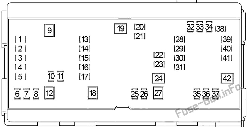
2003 Dodge Ram 2500 Fuse Box Diagram
So, you're diving into the electrical system of your 2003 Dodge Ram 2500? Smart move. Understanding the fuse box diagram is absolutely crucial whether you're tackling a minor electrical glitch, installing aftermarket accessories, or just want to get better acquainted with your truck's inner workings. This isn't just some pretty picture; it's your roadmap to keeping your Ram's electrical heart beating strong.
Purpose of the Fuse Box Diagram
Why bother with this diagram? Well, imagine trying to rewire your house without knowing which breaker controls which outlet. Chaos, right? The fuse box diagram is your electrical breaker panel equivalent for your Ram. It helps you:
- Diagnose Electrical Problems: If your headlights suddenly quit working, the diagram points you to the headlight fuse.
- Replace Blown Fuses: Identifying the correct fuse is essential to restoring functionality without damaging other components.
- Install Accessories: Safely tapping into the electrical system for things like auxiliary lights, winches, or upgraded stereos requires knowing which circuits can handle the extra load.
- Understand Your Truck's Electrical System: Gain a deeper understanding of how different components are powered and protected.
Key Specs and Main Parts of the Fuse Box
The 2003 Dodge Ram 2500 actually has *two* primary fuse boxes: the Power Distribution Center (PDC) under the hood and the Central Junction Box (CJB) inside the cabin. Let's break them down:
Power Distribution Center (PDC)
Located under the hood, usually near the battery, the PDC houses high-amperage fuses and relays that control major systems like the starter, alternator, fuel pump, and cooling fans. This is where you'll find the heavy-duty protection for the core functions of your truck. Key components you’ll find here include:
- Fuses: Ranging from small blade fuses to larger cartridge fuses.
- Relays: Electrically operated switches that control high-current circuits, often used for headlights, horns, and other high-draw accessories.
- Fuse Puller: A small plastic tool (often located on the PDC cover) used to safely remove fuses.
Central Junction Box (CJB)
The CJB is found inside the cab, typically under the dashboard on the driver's side. It handles lower-amperage circuits, controlling interior lights, power windows, door locks, radio, and other convenience features. Key components you'll find here:
- Fuses: Mostly standard blade fuses.
- Relays: Similar to the PDC relays, but typically controlling lower-power functions.
Important Note: Fuse amperage ratings are critical. Replacing a fuse with one of a higher amperage can overload the circuit and potentially cause a fire. Always use the correct amperage rating as specified in the diagram.
Understanding the Fuse Box Diagram Symbols
The diagram isn’t just a random layout of squares and lines. It uses specific symbols to represent different components and connections. Here's a rundown of some common symbols you'll encounter:
- Fuses: Typically represented by a squiggly line inside a rectangle or square. The amperage rating is usually printed next to the symbol (e.g., "10A," "20A").
- Relays: Represented by a square or rectangle with internal components that indicate the coil and contacts.
- Lines: Solid lines indicate a direct electrical connection. Dashed lines might indicate a ground connection or a control signal.
- Colors: Some diagrams use colors to differentiate between different circuits. For example, a red line might indicate a power wire, while a black line indicates a ground.
Each fuse and relay is usually labeled with a code or description. Refer to the legend on the diagram to understand what each label represents. Common labels include abbreviations like "IGN" (ignition), "ECM" (engine control module), "PCM" (powertrain control module), "PWR WDO" (power windows), and "HDLP" (headlamp).
How It Works: A Simplified Explanation
Think of the electrical system as a network of interconnected circuits. Each circuit is designed to power a specific component or group of components. The fuse acts as a safety valve. If the current in a circuit exceeds the fuse's amperage rating (due to a short circuit, overload, or faulty component), the fuse's internal element melts, breaking the circuit and preventing damage to other components. The relay acts as a remote switch, allowing a low-current signal to control a high-current circuit.
For example, when you turn on your headlights, the headlight switch sends a low-current signal to the headlight relay. The relay then closes, allowing high-current power to flow from the battery, through the headlight fuse, and to the headlights. If the headlights draw too much current (perhaps due to a short circuit in the wiring), the headlight fuse will blow, cutting off power to the headlights and preventing further damage.
Real-World Use: Basic Troubleshooting Tips
Here are some practical troubleshooting tips using the fuse box diagram:
- Identify the Problem: What's not working? Headlights, radio, power windows?
- Consult the Diagram: Locate the fuse or relay associated with the malfunctioning component in the fuse box diagram.
- Inspect the Fuse: Visually inspect the fuse. A blown fuse will have a broken filament inside. You can also use a multimeter to check for continuity across the fuse terminals. No continuity means the fuse is blown.
- Replace the Fuse: Use a fuse puller to remove the blown fuse and replace it with a new fuse of the *same* amperage rating.
- Test the Component: Turn on the component and see if it works.
- If the Fuse Blows Again: If the new fuse blows immediately, there's likely a short circuit or overload in the circuit. Further diagnosis is needed. This could involve checking the wiring, connectors, and the component itself.
- Relay Testing: Relays can be trickier to test. You can swap a relay with a known good relay of the same type (if available) to see if that resolves the issue. You can also use a multimeter to check the relay's coil and contacts.
Safety: Handle with Care!
Working with electrical systems can be dangerous. Here are some safety precautions:
- Disconnect the Battery: Before working on the electrical system, disconnect the negative (-) battery cable. This will prevent accidental short circuits and electrical shocks.
- Use Insulated Tools: Use tools with insulated handles to prevent electrical shocks.
- Never Bypass a Fuse: Never bypass a fuse by using a wire or other conductive material. This can overload the circuit and cause a fire.
- Be Careful Around High-Voltage Components: Components like the ignition coil and alternator can generate high voltages. Avoid touching these components while the engine is running.
- High-Risk Components: The PCM (Powertrain Control Module) and ECM (Engine Control Module) are extremely sensitive to voltage fluctuations. Always disconnect the battery before working on any circuits connected to these modules to prevent damage.
Remember, if you're not comfortable working with electrical systems, it's always best to consult a qualified mechanic.
We have the complete 2003 Dodge Ram 2500 Fuse Box Diagram available for download. Having a digital copy on your phone or tablet can be invaluable when you're working on your truck. You can download it by clicking [link to download here - REPLACE WITH ACTUAL LINK]. This will provide you with a high-resolution, printable version for easy reference.