2003 Dodge Ram Ignition Switch Wiring Diagram
Let's dive into the 2003 Dodge Ram ignition switch wiring diagram. Understanding this circuit is crucial for a variety of tasks, from diagnosing starting problems to performing security system modifications or even installing remote start systems. It’s a relatively straightforward system, but knowing the ins and outs of the wiring can save you time, money, and frustration.
Purpose of the Ignition Switch Wiring Diagram
The ignition switch wiring diagram is your roadmap to understanding how the ignition system in your 2003 Dodge Ram is wired. It serves several vital purposes:
- Troubleshooting Starting Problems: If your truck won't start, this diagram helps you pinpoint whether the ignition switch is the culprit or if the issue lies elsewhere (starter, battery, etc.).
- Security System Installation: When installing an aftermarket alarm or remote start, you need to identify specific wires to interrupt or tap into for proper functionality. The diagram tells you exactly which wires control which functions.
- Wiring Repairs: Over time, wires can become damaged, corroded, or disconnected. The diagram guides you in repairing or replacing these wires correctly.
- Understanding Vehicle Electrics: Even if you're not currently facing a problem, studying the diagram gives you a deeper understanding of how the vehicle's electrical system functions.
Key Specs and Main Parts
The 2003 Dodge Ram's ignition system is designed around several key components:
- Battery: The source of all electrical power in the vehicle. Typically a 12V system.
- Ignition Switch: This is the mechanical switch, usually located on the steering column, that controls the flow of power to various circuits depending on its position (Off, Accessory, Run, Start).
- Starter Relay: A high-current switch controlled by the ignition switch's 'Start' position. It allows the lower-current ignition switch to control the high-current starter motor.
- Starter Motor: The electric motor that cranks the engine.
- PCM (Powertrain Control Module): The vehicle's computer. The ignition switch provides a signal to the PCM indicating when the engine is being started or running. The PCM controls many functions, including fuel injection and ignition timing.
- ASD Relay (Automatic Shutdown Relay): This relay provides power to the fuel injectors and ignition coil. It's controlled by the PCM and is de-energized if the PCM detects a problem.
- Fuses: Protective devices designed to blow and interrupt the circuit if an overcurrent condition occurs.
Symbols, Lines, and Colors Explained
Understanding the symbols used in the wiring diagram is crucial for interpreting it correctly. Here are some common elements:
- Solid Lines: Represent wires. The thicker the line, the heavier gauge the wire (i.e., able to carry more current).
- Dashed Lines: Often indicate wires within a harness or a ground connection to the vehicle's chassis.
- Circles: Represent terminals or connectors.
- Squares/Rectangles: Can represent components like relays, switches, or fuses. The specific symbol within the square will identify the component type.
- Ground Symbol (Usually three horizontal lines, decreasing in size): Indicates a connection to the vehicle's chassis, providing a return path for the electrical current.
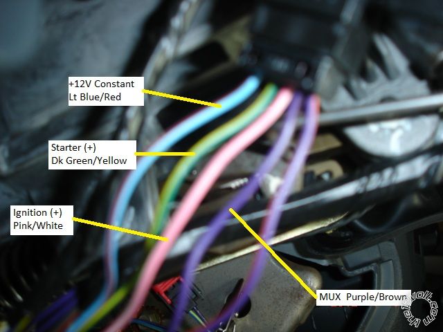
- Color Codes: Wires are typically color-coded for easy identification. Common colors include:
- Red (RD): Usually power from the battery.
- Black (BK): Typically ground.
- Orange (OR): Often accessory power.
- Yellow (YL): Often ignition power.
- Dark Blue (DB): Can be used for various signals.
- Light Blue (LB): Can be used for various signals.
- Green (GN): Can be used for various signals.
- White (WT): Can be used for various signals.
Connectors are generally identified with a code, e.g. C101, C203. These codes help you locate the physical connector in the vehicle. Relays can also be identified with their location number in the fuse box or relay box.
How It Works: The Ignition Sequence
Let's walk through a simplified version of how the ignition system operates:
- Off Position: No circuits are powered, except for possibly the clock or memory functions requiring constant power.
- Accessory (ACC) Position: Power is supplied to the radio, cigarette lighter (if equipped), and other accessory circuits. This is generally a low-current circuit.
- Run (ON) Position: Power is supplied to the PCM, fuel pump, ignition system (coil), and other essential engine management components. This is the normal operating position when the engine is running. The ASD relay is energized, supplying power to the fuel injectors and ignition coil(s).
- Start Position: In addition to the 'Run' circuits, the 'Start' position energizes the starter relay. The starter relay then sends a high-current signal to the starter motor, causing it to crank the engine. Once the engine starts, you release the key, and it springs back to the 'Run' position. The PCM monitors signals from the crankshaft and camshaft position sensors to control fuel injection and ignition timing.
Real-World Use: Basic Troubleshooting
Here's how you might use the wiring diagram to troubleshoot a no-start condition:
- Check the Battery: Ensure the battery is fully charged and the connections are clean and tight. A dead or weak battery is the most common cause of starting problems. Use a multimeter to verify the voltage. It should be above 12V.
- Check Fuses: Use the wiring diagram to identify the fuses related to the ignition switch, starter relay, and PCM. Use a test light or multimeter to check for continuity across each fuse. Never replace a blown fuse with a higher amperage fuse!
- Check the Starter Relay: Locate the starter relay. You can test it by swapping it with a known good relay (e.g., from the horn circuit). If the engine starts with the swapped relay, the original relay is faulty. You can also test the relay directly using a multimeter and applying voltage to the control circuit to see if it clicks and the contacts close.
- Check for Voltage at the Starter Motor: With the ignition switch in the 'Start' position, use a multimeter to check for voltage at the starter motor's solenoid terminal. If you have voltage but the starter doesn't crank, the starter motor itself is likely faulty.
- Check the Ignition Switch Output: Use the diagram to identify the 'Start' wire coming from the ignition switch. Use a multimeter to check for voltage on this wire when the key is in the 'Start' position. If there's no voltage, the ignition switch is likely faulty.
Important Note: Always disconnect the negative battery terminal before performing any electrical work to prevent shorts and potential damage.
Safety Considerations
Working with automotive electrical systems involves potential risks. Here are some key safety precautions:
- Battery Safety: Batteries contain corrosive acid and can produce explosive gases. Wear eye protection and avoid sparks near the battery.
- High-Current Circuits: The starter circuit is a high-current circuit. Shorting this circuit can cause severe burns, fires, and damage to the vehicle.
- Airbag System: The airbag system is sensitive and can be accidentally deployed if not handled correctly. If you need to work near the airbag system, disconnect the battery and wait at least 10 minutes before proceeding. (Refer to your service manual for specific procedures related to the airbag system).
- Fuel System: Working near the fuel system requires extra caution. Fuel is flammable, so avoid sparks and open flames. Depressurize the fuel system before disconnecting any fuel lines.
Always consult the vehicle's service manual for specific safety procedures and warnings.
If you're unsure about any aspect of the electrical system, it's best to consult a qualified mechanic. Incorrect wiring can damage the vehicle's computer or other components.
We have the complete 2003 Dodge Ram Ignition Switch Wiring Diagram file ready for you to download. This detailed schematic will be invaluable in your diagnostics and repairs. Be sure to print it out and keep it handy whenever you're working on your Ram's electrical system.