2003 Ford F150 Stereo Wiring Harness
Understanding the 2003 Ford F-150 stereo wiring harness is crucial for a variety of automotive tasks, from simply replacing a blown fuse to installing a sophisticated aftermarket audio system. This article provides a detailed guide to interpreting the wiring diagram for your truck's audio system, empowering you to troubleshoot problems, upgrade your sound, and generally work with confidence on your F-150's electrical components.
Purpose of Understanding the Wiring Diagram
Why bother learning about this seemingly complex web of wires? The wiring diagram is your roadmap to the audio system. It's essential for:
- Repairing Damaged Wiring: Identifying shorts, breaks, or corrosion in the harness.
- Installing Aftermarket Stereos: Ensuring proper connections to avoid damaging your new head unit or the truck's electrical system.
- Adding Amplifiers and Subwoofers: Integrating new components seamlessly into the existing audio architecture.
- Troubleshooting Audio Problems: Pinpointing the source of issues like no sound, distortion, or intermittent operation.
- Understanding the System's Functionality: Gaining a deeper understanding of how the entire audio system is wired and operates.
Key Specs and Main Parts of the 2003 F-150 Stereo Wiring Harness
The 2003 Ford F-150 stereo wiring harness is primarily located behind the radio in the dashboard. It connects the radio (or "head unit") to the vehicle's power supply, speakers, antenna, and potentially other components like a factory amplifier (if equipped). Knowing the pinout of the harness – which is the specific arrangement of wires and their corresponding functions – is paramount.
Here's a breakdown of the key components and specifications. This is a generalized overview; specific configurations may vary based on trim level (e.g., XL, XLT, Lariat) and options packages.
- Power Wires: These provide the necessary electrical current to operate the radio. Typical connections include:
- +12V Constant (Battery): Provides constant power, even when the ignition is off, to retain radio presets and memory.
- +12V Switched (Ignition): Supplies power only when the ignition is in the "Accessory" or "On" position.
- Ground: Provides a return path for the electrical current. It's crucial for a proper ground connection to ensure optimal performance and prevent electrical noise.
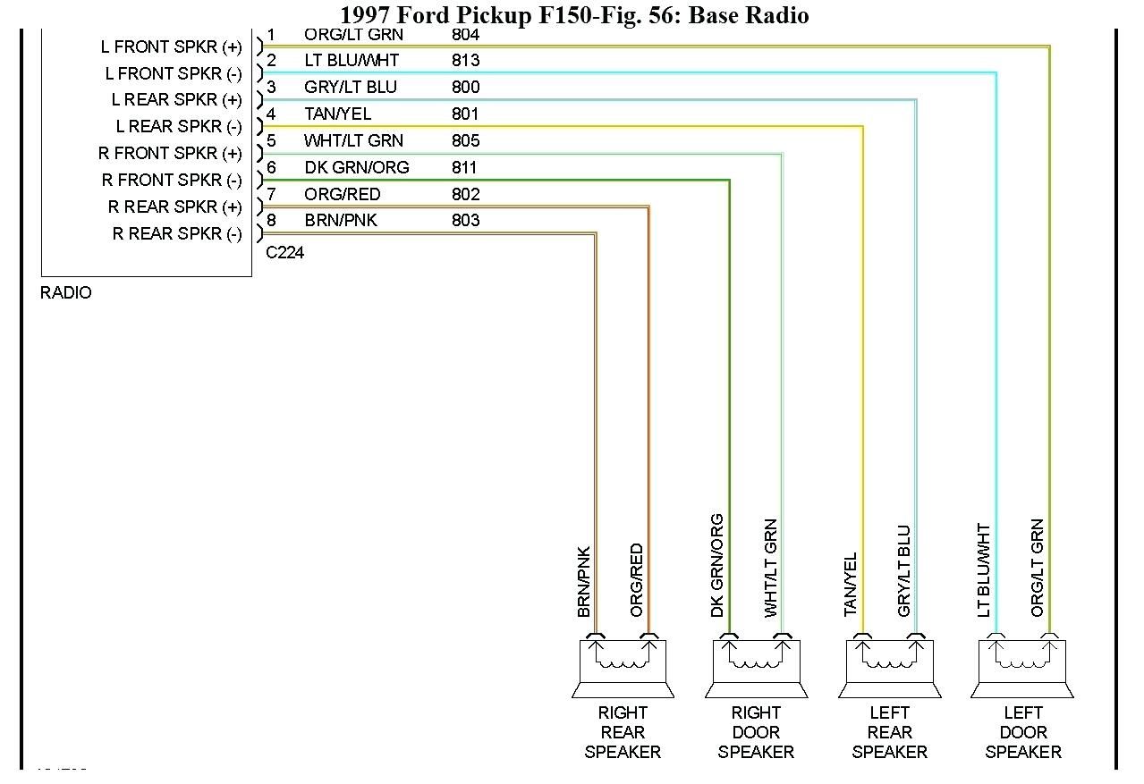
- Speaker Wires: These wires carry the audio signal from the radio to the speakers. Each speaker has two wires: a positive (+) and a negative (-) connection. The 2003 F-150 typically has four speaker outputs:
- Front Left (+) and (-)
- Front Right (+) and (-)
- Rear Left (+) and (-)
- Rear Right (+) and (-)
- Antenna Wire: A coaxial cable that connects the radio to the antenna, allowing it to receive radio signals.
- Illumination Wire: Dims the radio's display when the headlights are turned on. This is often a low-voltage signal.
- Remote Turn-On Wire (Optional): If the vehicle has a factory amplifier, this wire (also known as an amplifier turn-on lead) signals the amplifier to turn on when the radio is powered on. This is a 12V trigger signal.
- Data Bus Wires (Optional): Some radios may communicate with the vehicle's computer system via data bus wires (e.g., CAN bus). These are typically used for features like steering wheel controls.
The wiring harness itself is typically a multi-pin connector that plugs directly into the back of the radio. Aftermarket radio adapters are available to facilitate the installation of new radios without cutting into the factory wiring harness. These adapters plug into the factory harness and provide standard connections (e.g., RCA connectors for amplifiers, color-coded wires for speakers) for the new radio.
Decoding the Wiring Diagram: Symbols, Lines, and Colors
A wiring diagram uses standardized symbols and conventions to represent electrical components and their connections. Understanding these symbols is key to interpreting the diagram accurately.
- Lines: Solid lines represent wires, while dashed lines may indicate shielding or communication lines.
- Colors: Each wire is color-coded, and the diagram will include a key indicating which color corresponds to which function. Common colors include:
- Red: Usually +12V Constant (Battery)
- Yellow: Usually +12V Switched (Ignition)
- Black: Ground
- White: Often used for speaker wires
- Green: Often used for speaker wires
- Gray: Often used for speaker wires
- Purple: Often used for speaker wires
- Symbols:
- A circle with a line through it: Represents a ground connection.
- A zigzag line: Represents a resistor.
- A rectangle: Can represent various components, depending on the label (e.g., radio, amplifier).
- A coil symbol: Represents an inductor.
- A capacitor symbol: Represents a capacitor.
The diagram will also include labels indicating the function of each wire (e.g., "Battery," "Ground," "Front Left Speaker +"). Pay close attention to these labels to ensure you're making the correct connections. The diagrams often include pin numbers indicating the location of the wire connection within the harness.
How It Works: Signal Flow
The audio system operates by receiving power from the vehicle's battery and ignition switch. The radio processes audio signals from various sources (e.g., radio antenna, CD player, auxiliary input). The amplified audio signals are then sent to the speakers via the speaker wires. The ground wires provide a return path for the electrical current, completing the circuit.
In systems with a factory amplifier, the radio sends a low-level audio signal to the amplifier, which then amplifies the signal and sends it to the speakers. The remote turn-on wire ensures that the amplifier turns on and off with the radio.
Understanding this flow of information is helpful for troubleshooting. For instance, if there's no sound from one speaker, you can trace the signal path from the radio to the speaker, checking for breaks in the wiring or a faulty speaker. Knowing if your system has an amplifier is a key element to this troubleshooting.
Real-World Use: Basic Troubleshooting Tips
Here are some common troubleshooting scenarios and how the wiring diagram can help:
- No Power to the Radio: Use a multimeter to check for voltage on the +12V Constant and +12V Switched wires. Verify the ground connection. Refer to the wiring diagram to locate the fuses that protect these circuits and check their condition.
- No Sound from One Speaker: Check the speaker wiring connections at both the radio and the speaker. Use a multimeter to test the speaker wire for continuity. You can also test the speaker itself with an ohmmeter. A reading of infinite resistance (open circuit) indicates a blown speaker.
- Distorted Sound: Check for loose or corroded wiring connections. Ensure the speaker wires are not shorted to ground. A wiring diagram helps you quickly identify and inspect the relevant wires.
- Radio Turns Off and On Intermittently: Check the +12V Constant and +12V Switched wiring connections. A loose connection can cause the radio to lose power intermittently. Vibration during driving can exacerbate this issue.
Safety Precautions
Working with automotive electrical systems can be dangerous. Always take the following precautions:
- Disconnect the Negative Battery Terminal: This is the single most important safety precaution. Disconnecting the battery prevents accidental shorts and electrical shocks.
- Use Proper Tools: Use insulated tools designed for automotive electrical work.
- Work in a Well-Lit Area: Good lighting makes it easier to see what you're doing and reduces the risk of mistakes.
- Avoid Working on Live Wires: If you must work on live wires, use extreme caution and wear insulated gloves.
- Be Aware of the Airbag System: The airbag system contains sensitive components that can be accidentally deployed if mishandled. Refer to the vehicle's service manual for instructions on disabling the airbag system before working near it. Incorrect handling can result in serious injury.
Specifically, the constant +12V wire is always "hot", meaning it has voltage even with the ignition off. Disconnecting the battery is crucial to prevent shorts when working with this wire. Shorting this wire to ground can blow fuses, damage the radio, or even start a fire.
By understanding the 2003 Ford F-150 stereo wiring harness and taking appropriate safety precautions, you can confidently tackle a wide range of automotive audio projects. This knowledge empowers you to maintain, upgrade, and troubleshoot your truck's audio system effectively.
We have access to the detailed wiring diagram file for the 2003 Ford F-150. If you need the complete wiring diagram, it's available for download. This detailed diagram will provide specific pinouts and color codes that apply to your 2003 F-150 model.