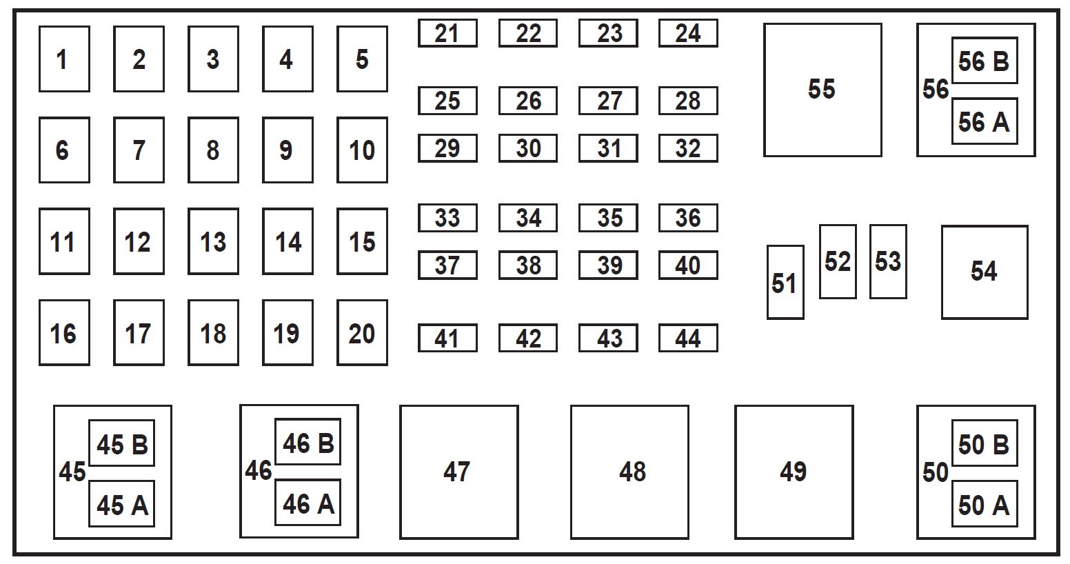
2003 Ford Ranger Fuse Box Diagram Under Hood
Understanding the fuse box diagram for your 2003 Ford Ranger is crucial for a variety of reasons. Whether you're tackling a simple repair, performing aftermarket modifications, or simply trying to understand your truck's electrical system, having this knowledge will save you time, money, and potential headaches. This article provides a detailed explanation of the under-hood fuse box diagram, enabling you to confidently navigate its components and functions.
Purpose: Why Bother With the Fuse Box Diagram?
The fuse box diagram isn't just a pretty picture; it's your roadmap to the electrical heart of your Ranger. It serves several vital purposes:
- Troubleshooting Electrical Issues: When a circuit malfunctions, the first step is to check the corresponding fuse. The diagram identifies the fuse for specific components like headlights, windshield wipers, or the radio.
- Performing Repairs: Knowing which fuse protects which circuit prevents accidental damage when working on specific components. Disconnecting the appropriate fuse isolates the circuit.
- Installing Aftermarket Accessories: Adding things like aftermarket lights or a new stereo requires tapping into the electrical system. The diagram helps you identify safe and appropriate circuits to use for power.
- General Understanding: Simply put, understanding the fuse box is about understanding your truck's electrical architecture. It gives you insight into how different systems are interconnected.
Key Specs and Main Parts of the 2003 Ford Ranger Under-Hood Fuse Box
The 2003 Ford Ranger's under-hood fuse box is typically located on the driver's side, near the battery. It's a black plastic enclosure that houses a collection of fuses and relays. Let's break down the key components:
- Fuses: These are the sacrificial components that protect circuits from overcurrent. They are rated in Amperes (Amps or A), indicating the amount of current they can handle before blowing. Different circuits require different amperage ratings.
- Relays: These are electrically operated switches. They allow a low-current circuit to control a high-current circuit. For example, the headlight relay allows the dashboard switch (low current) to control the headlights (high current).
- Fuse Puller: A small plastic tool, often clipped inside the fuse box lid, used to safely remove fuses. Avoid using metal tools as they can cause shorts.
- The Diagram (The Star of the Show): This is a label, usually affixed to the inside of the fuse box lid, depicting the layout of the fuses and relays, along with their corresponding functions. It's also available for download from various sources (more on that later).
Understanding the fuse and relay layout is paramount. While the diagram is invaluable, physically inspecting the fuse box and comparing it to the diagram is always a good practice. Fuse box layouts may vary slightly depending on the specific Ranger model and options package.
Decoding the Symbols: Lines, Colors, and Icons
The fuse box diagram uses a standardized set of symbols to represent different components and their connections. Here's a breakdown:
- Lines: Lines on the diagram represent electrical wires or circuits. A thicker line usually indicates a higher-current circuit.
- Fuse Symbols: A fuse is typically represented by a zigzag line inside a rectangular box. Sometimes it is represented by just a straight horizontal line. The amperage rating (e.g., 10A, 20A) is usually written next to the symbol.
- Relay Symbols: A relay is represented by a coil and a switch. The coil represents the electromagnet that activates the switch. The switch represents the contacts that open or close the circuit.
- Component Icons: The diagram often uses icons or abbreviations to represent specific components, such as:
- Headlight: Often represented by a light bulb icon or "HDL".
- Windshield Wiper: Sometimes depicted by a wiper blade icon or "WIP".
- Radio: Usually a speaker icon or "RADIO".
- PCM: Powertrain Control Module (engine computer).
- GEM: Generic Electronic Module (controls various body functions).
- Colors: Some diagrams use color coding to differentiate between different types of circuits or voltage levels. However, on the 2003 Ranger diagram, the color coding is usually just to make it easier to read. Don't assume the colors in the diagram are the exact wire colors under the hood. Always use a multimeter to verify.
How It Works: The Electrical Flow
Understanding how the electrical system works in conjunction with the fuse box diagram is key to effective troubleshooting.
- Power Source: The battery provides the initial power source for the entire electrical system.
- Distribution: Power flows from the battery to the fuse box, which acts as a central distribution point.
- Circuit Protection: As power flows through the fuse box, it passes through fuses. If a circuit experiences an overcurrent (e.g., due to a short circuit), the fuse blows, interrupting the flow of electricity and preventing damage to the component and wiring.
- Relay Control: For high-current devices, a relay is used. A low-current signal from a switch in the cabin activates the relay, which then closes the high-current circuit, powering the device.
- Component Operation: Once the circuit is complete (and the fuse is intact), the electrical component (e.g., headlight, radio) receives power and performs its intended function.
Real-World Use: Basic Troubleshooting Tips
Let's say your headlights aren't working. Here's how you can use the fuse box diagram to troubleshoot the issue:
- Consult the Diagram: Locate the fuse labeled "Headlights" (or "HDL") on the diagram. Note its amperage rating.
- Locate the Fuse: Open the fuse box and find the fuse in the corresponding location.
- Inspect the Fuse: Use the fuse puller to remove the fuse. Visually inspect it. If the thin wire inside the fuse is broken, the fuse is blown.
- Replace the Fuse: Replace the blown fuse with a new fuse of the same amperage rating. Never use a higher amperage fuse, as this can create a fire hazard.
- Test: Turn on the headlights to see if they now work.
- If the Fuse Blows Again: If the new fuse immediately blows, there is a short circuit in the headlight circuit. Further diagnosis is required, which may involve tracing the wiring and checking for damaged insulation.
Safety: Respect the Electrical System
Working with automotive electrical systems can be dangerous. Always observe these safety precautions:
- Disconnect the Battery: Before working on any electrical components, disconnect the negative terminal of the battery to prevent accidental shorts.
- Use Proper Tools: Use insulated tools to avoid electrical shock.
- Never Bypass Fuses: Bypassing a fuse creates a serious fire hazard. Always replace blown fuses with fuses of the correct amperage rating.
- High-Risk Components: Be particularly cautious when working with components that carry high voltage or current, such as the starter motor circuit and the alternator circuit.
WARNING: The charging system can carry high voltages. Never touch exposed wires or terminals while the engine is running. Disconnect the negative battery cable before performing any electrical work.
Working with electrical systems requires careful attention to detail. Always consult the wiring diagrams and follow proper safety procedures. If you are not comfortable working with electrical systems, seek the assistance of a qualified mechanic.
We have a digital copy of the 2003 Ford Ranger Under-Hood Fuse Box Diagram readily available. Please contact us, and we'll happily provide you with a downloadable file.