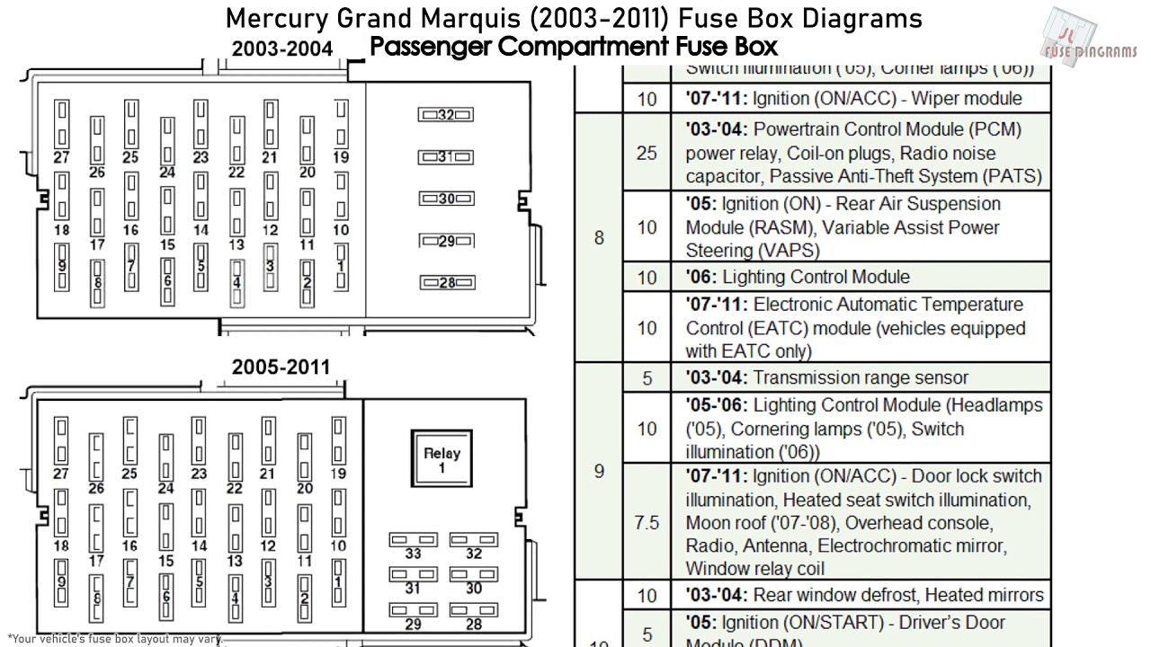
2003 Mercury Grand Marquis Fuse Box Diagram
The 2003 Mercury Grand Marquis, a classic full-size sedan, relies on a network of electrical circuits to power everything from its headlights to its power windows. Understanding the fuse box diagram for this model is crucial for anyone performing DIY repairs, modifications, or even just diagnosing electrical issues. This article provides a detailed breakdown of the 2003 Grand Marquis fuse box, covering its purpose, components, symbols, functionality, troubleshooting, and safety considerations. We’ll help you confidently navigate this vital aspect of your vehicle's electrical system.
Purpose of the Fuse Box Diagram
Why is a fuse box diagram so important? Simply put, it’s your roadmap to the vehicle’s electrical system. It serves several key purposes:
- Troubleshooting Electrical Problems: When an electrical component fails (e.g., a turn signal stops working), the diagram helps you quickly identify the corresponding fuse or relay.
- Performing Repairs: Before attempting any electrical repair, the diagram helps you locate the circuits you'll be working with, ensuring you don't accidentally damage unrelated components.
- Adding Aftermarket Accessories: If you're installing a new stereo, alarm system, or auxiliary lights, the diagram is essential for tapping into the correct power source and protecting your vehicle's electrical system.
- General Understanding: Even if you’re not actively working on your car, understanding the fuse box layout gives you a better grasp of how its electrical systems are organized.
Key Specs and Main Parts
The 2003 Mercury Grand Marquis features multiple fuse boxes, but we'll primarily focus on the two most important ones: the interior fuse box and the power distribution box (engine compartment).
- Interior Fuse Box: Typically located under the dashboard, often on the driver's side. It houses fuses for interior components like lights, radio, power windows, and instrument panel.
- Power Distribution Box (Engine Compartment): Found under the hood, near the engine. This box contains fuses and relays for high-current components such as the starter motor, headlights, windshield wipers, and fuel pump. It also houses relays that control many of these functions.
Key specs to consider include the ampere (amp) rating of each fuse. Fuses are rated in amps (A), indicating the maximum current they can safely carry before blowing (breaking the circuit). The correct amperage rating is crucial; using a fuse with a higher rating can damage components, while a lower rating can cause nuisance blowing.
Main parts within each fuse box include:
- Fuses: These are the sacrificial links in the circuit. They are designed to melt and break the circuit if the current exceeds their rating, preventing damage to other components. Common fuse types include blade fuses (ATO/ATC, mini-blade) and cartridge fuses.
- Relays: These are electromagnetic switches that control high-current circuits using a low-current control signal. Relays are essential for systems like headlights and starters, where the switch on the dashboard can't handle the high current directly.
- Circuit Breakers: Some circuits, especially those related to power windows or locks, may use circuit breakers. These are resettable fuses that trip (open the circuit) when overloaded and automatically reset after a cooling period.
- Connectors and Wiring: These connect the fuses, relays, and circuit breakers to the vehicle's wiring harness.
Symbols: Deciphering the Diagram
Fuse box diagrams use symbols and abbreviations to represent different components and their functions. Understanding these symbols is key to interpreting the diagram correctly.
- Lines: Lines represent electrical wires or circuits. The thickness of the line may indicate the wire gauge (thickness).
- Boxes: Boxes typically represent fuses, relays, or circuit breakers.
- Numbers: Numbers next to each fuse or relay indicate its position in the fuse box. The diagram will have a legend that maps each number to a specific circuit and amperage rating.
- Abbreviations: Common abbreviations include:
- PWR: Power
- IGN: Ignition
- ACC: Accessory
- PCM: Powertrain Control Module (Engine Computer)
- GEM: Generic Electronic Module
- ABS: Anti-lock Braking System
- LTR: Lighter
- Color Coding: Some diagrams use color coding to differentiate circuits. For example, a red line might indicate a constant power supply, while a blue line might indicate an ignition-switched power supply. However, do not rely on this as wire colors in the vehicle may vary.
The diagram will also show the amperage rating of each fuse, usually indicated by a number followed by "A" (e.g., 15A for a 15-amp fuse).
How It Works
The fuse box is essentially a central distribution point for electrical power. The battery provides the initial electrical energy. This power is then routed through the fuse boxes, where it is distributed to various circuits throughout the vehicle. Each circuit is protected by a fuse or circuit breaker.
When a circuit experiences an overload or short circuit (e.g., a wire chafes and grounds to the car's body), the current flow increases dramatically. This excessive current causes the fuse to heat up and melt its internal element, breaking the circuit and preventing further damage.
Relays act as remote-controlled switches. A low-current signal from a switch (e.g., headlight switch) activates the relay, which then closes a high-current circuit to power the intended component (e.g., headlights). This allows for the use of smaller, more convenient switches while still controlling high-power devices. Think of it like a light switch that controls a powerful spotlight using just a small amount of electricity.
Real-World Use: Basic Troubleshooting Tips
Here's a basic troubleshooting process using the fuse box diagram:
- Identify the Problem: Determine which electrical component is not working.
- Consult the Diagram: Locate the corresponding fuse or relay for the affected component in the fuse box diagram.
- Inspect the Fuse: Remove the fuse and visually inspect it. A blown fuse will have a broken filament or a darkened appearance.
- Test the Fuse: Use a multimeter set to continuity mode to test the fuse. A good fuse will show continuity (a closed circuit), while a blown fuse will show no continuity (an open circuit).
- Replace the Fuse: If the fuse is blown, replace it with a fuse of the exact same amperage rating.
- Test the Component: After replacing the fuse, test the affected component to see if it now works.
- If the Fuse Blows Again: If the new fuse blows immediately or shortly after replacement, there is likely a short circuit or overload in the circuit. This requires further investigation and may require the assistance of a qualified mechanic. Do not simply install a higher amperage fuse.
- Check the Relay: If a relay is suspected, you can try swapping it with a known good relay of the same type. If the problem resolves, the relay is likely faulty. You can also test a relay with a multimeter, but this requires knowledge of relay pinouts and testing procedures.
Safety Considerations
Working with automotive electrical systems can be dangerous. Here are some crucial safety precautions:
- Disconnect the Battery: Before working on any electrical circuits, disconnect the negative (-) battery cable to prevent accidental shorts and shocks.
- Use Proper Tools: Use insulated tools designed for automotive electrical work.
- Avoid Water: Never work on electrical systems in wet conditions.
- High-Current Components: Be extremely cautious when working with high-current components like the starter motor, alternator, and airbags. These components can deliver a powerful shock or cause serious injury. Always disconnect the battery and follow manufacturer's instructions carefully. Airbags should only be serviced by qualified technicians.
- Do Not Bypass Fuses: Never bypass a fuse with a wire or other conductive material. This eliminates the circuit protection and can lead to a fire or serious damage.
- Correct Fuse Amperage: Always use fuses with the correct amperage rating. Using a higher amperage fuse can overload the circuit and damage components.
Understanding the 2003 Mercury Grand Marquis fuse box diagram is essential for maintaining and repairing your vehicle's electrical system. By carefully following the diagram and adhering to safety precautions, you can confidently troubleshoot and resolve many common electrical issues. Remember, when in doubt, consult a qualified mechanic.
We have a high-resolution, downloadable PDF file of the 2003 Mercury Grand Marquis fuse box diagram available for you. This resource will provide a clear and detailed visual aid for your troubleshooting and repair needs. Feel free to download it to have it readily accessible whenever you're working on your Grand Marquis' electrical system.