2003 Mitsubishi Eclipse Radio Wiring Diagram
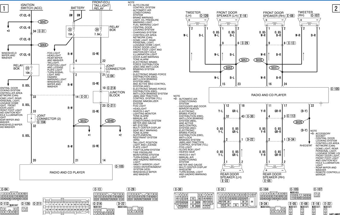
Alright, let's dive into the wiring diagram for the 2003 Mitsubishi Eclipse's radio. This isn't just some abstract chart; it's your roadmap for understanding, modifying, or repairing the audio system in your Eclipse. Whether you're upgrading speakers, installing a new head unit, chasing down a phantom drain, or simply trying to understand the electrical system, having this diagram is absolutely crucial. Think of it as the Rosetta Stone for your car's audio.
Why This Diagram Matters
The purpose of understanding your 2003 Eclipse radio wiring diagram boils down to a few key things:
- Troubleshooting Audio Issues: Diagnosing why your radio isn't working (no power, no sound, intermittent issues) becomes far simpler when you can trace the signal path and identify potential breaks in the circuit.
- Upgrading Your System: Installing a new aftermarket head unit, amplifier, or speakers requires you to tap into existing wiring. Knowing exactly what each wire does prevents accidental damage or electrical shorts.
- Learning Automotive Electrical: Even if you're not actively working on your radio, studying the diagram is a great way to learn the basics of automotive electrical systems.
- Restoring Originality: For those meticulous about keeping their Eclipse stock, the diagram helps ensure any replaced components are wired correctly to maintain the original functionality.
Key Specs and Main Parts
Before we get into the intricate details, let’s cover the key components that are shown on the diagram. These are the main players in your Eclipse's audio system:
- Head Unit (Radio): The central control unit for the entire system. It includes the tuner, amplifier, and controls for volume, tone, and source selection.
- Speakers: The output devices that convert electrical signals into audible sound. Your Eclipse likely has a combination of tweeters, woofers, and perhaps a subwoofer (depending on the trim level).
- Amplifier (Optional): Some Eclipse models came with a factory amplifier to boost the signal to the speakers. This is typically located under a seat or in the trunk.
- Antenna: Receives radio signals from broadcasting stations.
- Wiring Harnesses: Bundles of wires that connect all the components together. These harnesses usually have connectors that plug into the back of the head unit, amplifier, and speakers.
- Fuses: Protective devices that prevent overcurrent and damage to the electrical system. Knowing which fuse protects the radio circuit is essential for troubleshooting.
- Grounding Points: Crucial connection points where circuits are connected to the chassis of the car for a common ground. A bad ground can cause all sorts of electrical gremlins.
Symbols – Lines, Colors, and Icons
Understanding the symbols in the wiring diagram is key to deciphering its information.
Lines:
- Solid Lines: Represent wires. The thicker the line, the greater the current-carrying capacity of the wire.
- Dashed Lines: Can represent shielded cables or connections that are not always present (depending on options).
- Lines with Arrows: Indicate the direction of current flow.
Colors:
Wire colors are extremely important and are always indicated. Common colors and what they often represent include:
- Red: Typically a constant +12V power source.
- Yellow: Often a +12V accessory power source (switched with the ignition).
- Black: Always ground.
- Blue: Remote turn-on for amplifiers.
- White/Gray: Speaker wires. Often, one wire is a solid color and the other has a stripe.
The diagram will have a key that specifically defines each color and its function.
Icons:
- Circles: Represent connectors or junctions.
- Rectangles: Can represent components like the radio, amplifier, or even a fuse box.
- Ground Symbol: A series of horizontal lines decreasing in length, indicating a connection to the vehicle's chassis.
- Fuse Symbol: A squiggly line within a rectangle.
Pay attention to the notes accompanying the icons, as they often contain important information about the component.
How It Works
The 2003 Eclipse radio wiring diagram outlines how power and signals are distributed throughout the audio system. Here's a simplified breakdown:
- Power Supply: The radio receives power from two sources: a constant +12V (usually red) to maintain memory functions (like presets) and a switched +12V (usually yellow) that comes on when the ignition is turned on. These are protected by fuses in the fuse box.
- Grounding: The radio, amplifier, and speakers must be properly grounded to the vehicle's chassis (black wire). A poor ground connection can cause static, distortion, or even complete failure.
- Signal Input: The radio receives signals from the antenna for AM/FM broadcasts and from other sources like a CD player or auxiliary input.
- Signal Processing: The radio processes the incoming signal, amplifies it, and sends it to the speakers through the speaker wires.
- Speaker Output: The amplified signal travels through the speaker wires to the corresponding speakers (front left, front right, rear left, rear right).
- Amplifier (if equipped): On models with a factory amplifier, the radio sends a low-level signal to the amplifier, which then boosts the signal before sending it to the speakers.
Real-World Use – Basic Troubleshooting Tips
Let's put this knowledge to use with some common troubleshooting scenarios:
- Radio Has No Power: Check the fuses for the radio in the fuse box. Use the wiring diagram to identify the correct fuses. If the fuse is blown, replace it. If it blows again immediately, there's a short circuit somewhere in the wiring. Trace the power wires (red and yellow) using the diagram to find the short. A multimeter is indispensable here.
- No Sound From Speakers: First, check the speaker connections at the back of the radio and at the speakers themselves. Use the wiring diagram to verify that the correct wires are connected to the correct terminals. If the connections are good, use a multimeter to check for continuity in the speaker wires. A broken wire will prevent sound from reaching the speaker. If you have an amplifier, check its power and ground connections as well.
- Static or Distortion: Check the ground connections for the radio, amplifier, and speakers. Clean and tighten any loose or corroded connections. Try running a new ground wire directly from the component to the vehicle's chassis.
- Upgrading Speakers: The wiring diagram shows which wires go to each speaker. Make sure you connect the positive and negative terminals of the new speakers correctly to avoid damaging the amplifier or speakers. Pay close attention to the wire colors.
Safety – Highlight Risky Components
Working with automotive electrical systems can be dangerous if you're not careful. Here are some safety precautions to keep in mind:
- Disconnect the Battery: Always disconnect the negative battery terminal before working on any electrical components. This will prevent accidental shorts and electrical shocks.
- Use a Multimeter: A multimeter is essential for diagnosing electrical problems. Learn how to use it to check for voltage, continuity, and resistance.
- Avoid Cutting Wires: If possible, avoid cutting wires. Use wire taps or connectors to make splices. If you must cut a wire, make sure to properly insulate the connection afterwards.
- Be Careful with Fuses: Never replace a fuse with one of a higher amperage rating. This can overload the circuit and cause a fire. Always use the correct fuse rating specified in the owner's manual or on the fuse box cover.
- Airbags: Be extremely cautious when working near airbags. Improper wiring or accidental activation can cause serious injury. Consult a professional if you are unsure.
We have the complete 2003 Mitsubishi Eclipse Radio Wiring Diagram file available for download. This document provides a detailed schematic that you can use to guide your repairs, modifications, or upgrades. Refer to it carefully, and always prioritize safety when working on your car's electrical system. Remember, when in doubt, consult a qualified automotive electrician.