2003 Mitsubishi Eclipse Stereo Wiring Diagram
Let's dive into the 2003 Mitsubishi Eclipse stereo wiring diagram. This isn't just a piece of paper; it's your roadmap to understanding, modifying, or repairing the audio system in your Eclipse. Whether you're upgrading to a modern head unit, troubleshooting a blown speaker, or just curious about how it all connects, this diagram is essential. We'll break it down into manageable chunks, covering the key components, the meaning of the symbols, and how to apply this knowledge in the real world. And don't worry, we have the complete diagram available for you to download, linked at the end of this article.
Purpose of the Wiring Diagram
Why bother with a wiring diagram? Simple. It's the key to unlocking the secrets of your car's audio system. You might need it for:
- Stereo Replacement: Safely disconnecting the old stereo and connecting a new aftermarket unit requires understanding the pinouts and wire functions.
- Speaker Upgrades: Replacing factory speakers often involves identifying the correct speaker wires and polarity.
- Amplifier Installation: Tapping into the existing wiring harness for signal and power to an amplifier demands precise knowledge of the circuits.
- Troubleshooting: When your audio system malfunctions, the diagram helps you trace circuits, identify shorts, and pinpoint the source of the problem.
- Learning and Modification: For the curious DIYer, understanding the wiring is the first step to customizing and optimizing your sound system.
Key Specs and Main Parts
The 2003 Mitsubishi Eclipse audio system, in its stock configuration, typically consists of the following components. Keep in mind that trims (RS, GS, GT) can affect specific component locations and features:
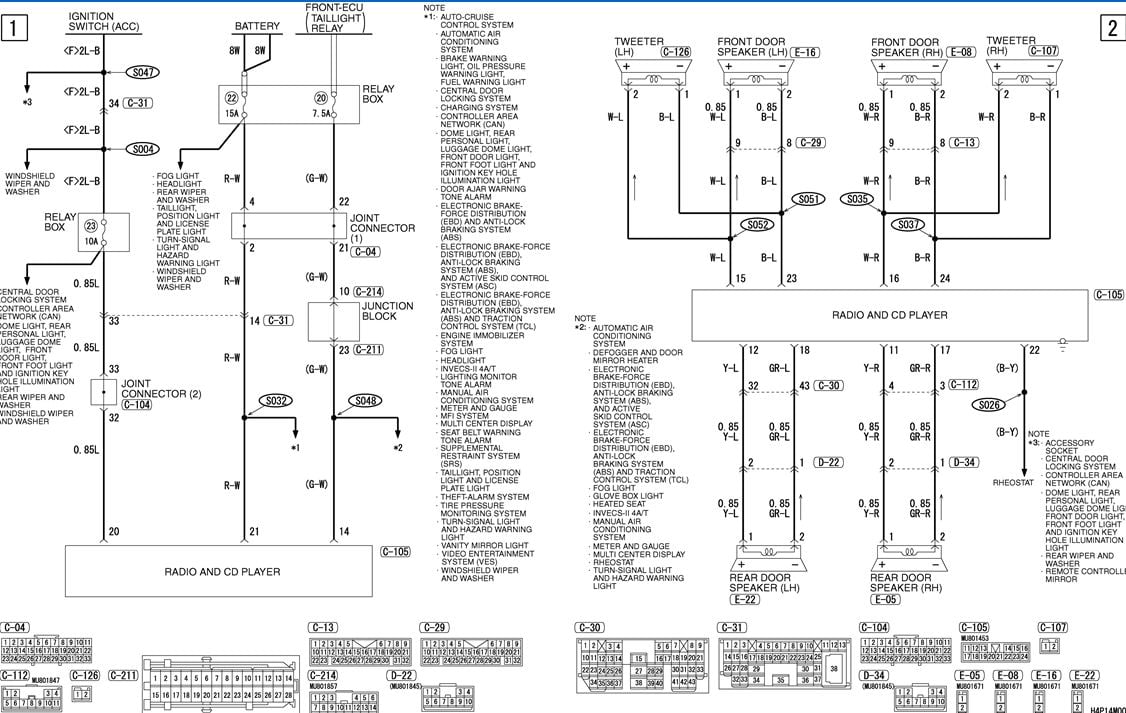
- Head Unit (Radio/CD Player): This is the heart of the system, providing the audio source and controlling other components. It outputs audio signals and receives power. The 2003 Eclipse used a standard DIN-sized head unit.
- Speakers: Generally, there are four speakers: two in the front doors and two in the rear deck or side panels. Some models may include tweeters.
- Wiring Harness: This is the collection of wires that connects all the components. It includes power, ground, speaker wires, remote turn-on (for amplifiers), and other control signals.
- Antenna: Receives radio signals.
- (Optional) Factory Amplifier: Some models, particularly those with premium sound systems, include a factory amplifier to boost the audio signal. If present, this will be located separately from the head unit, commonly under a seat or in the trunk.
The wiring diagram will detail the specific pins and functions for each of these components. The key is understanding the color codes and their corresponding function within the harness. Voltage is typically 12V DC.
Understanding the Symbols
A wiring diagram isn't just a bunch of lines; it's a language with its own set of symbols. Learning to read these symbols is crucial for accurate interpretation. Here are some common symbols and their meanings:
- Solid Lines: Represent wires. Thicker lines may indicate wires carrying higher current, such as power wires.
- Dashed Lines: Often represent shielding or ground connections.
- Color Codes: Each wire has a specific color code (e.g., Red/White, Blue/Yellow). These codes are essential for identifying the correct wires in the harness. Common color codes include:
- Red: Usually indicates a 12V constant power source.
- Yellow: Often a 12V switched power source (ignition-controlled).
- Black: Typically ground.
- White: Commonly used for speaker wires.
- Other colors (Green, Blue, Brown, etc.): Indicate specific functions, such as remote turn-on or illumination.
- Connectors: Represented by squares or circles with pins labeled. The diagram shows how the wires connect to these connectors.
- Ground Symbols: Indicate a connection to the vehicle's chassis ground.
- Component Symbols: Represent the head unit, speakers, amplifier, etc. These symbols are usually simplified representations of the actual components.
The 2003 Eclipse wiring diagram should clearly define the function of each pin in the connectors at the back of the head unit and any other components. Pay close attention to the legend provided with the diagram, as it will detail the specific symbols and abbreviations used.
How It Works: A Simplified Explanation
Let's trace a basic signal path. The head unit generates an audio signal. This signal is then sent through the wiring harness to the speakers. The head unit also provides power to itself and, potentially, a remote turn-on signal to an amplifier (if equipped). The ground wires provide a return path for the electrical current, completing the circuit.
When you turn on the ignition, the yellow wire (typically) provides power to the head unit. You can then select a source (radio, CD, etc.), and the head unit will output an audio signal. This signal travels through the speaker wires to the respective speakers, which convert the electrical signal into sound waves.
If you have a factory amplifier, the head unit sends a low-level audio signal to the amplifier. The amplifier boosts this signal and then sends it to the speakers. A remote turn-on wire from the head unit signals the amplifier to power on when the ignition is turned on.
Real-World Use: Basic Troubleshooting Tips
Here are some common issues and how the wiring diagram can help you troubleshoot:
- No Power to the Head Unit: Check the red (constant power) and yellow (switched power) wires with a multimeter to ensure they are receiving 12V. Also, check the ground connection. The wiring diagram shows you exactly which pins to test. A blown fuse is a common culprit as well.
- One Speaker Not Working: Use the wiring diagram to identify the speaker wires for that speaker. Check the connections at both the head unit and the speaker. You can also use a multimeter to test the continuity of the wires.
- Distorted Sound: This could be a speaker issue, but it could also be a wiring problem. Check for shorts or loose connections in the speaker wires. Also verify the speaker impedance matches what the head unit expects.
- Excessive Noise: Noise issues are often related to grounding problems. Ensure all ground connections are clean and secure. The wiring diagram will show you the location of the ground points.
Safety First!
Working with electrical systems in a car can be dangerous. Here are some essential safety precautions:
- Disconnect the Battery: Always disconnect the negative terminal of the battery before working on any electrical components. This prevents accidental shorts and shocks.
- Use a Multimeter: A multimeter is your best friend. It allows you to safely test voltages and continuity without damaging components.
- Work in a Well-Lit Area: Good lighting is essential for seeing what you're doing and avoiding mistakes.
- Avoid Working on Live Circuits: If possible, avoid working on circuits while the car is running or the ignition is on.
- Be Careful with Capacitors: Some audio components, particularly amplifiers, contain large capacitors that can store a dangerous charge even after the power is disconnected. Discharge these capacitors before working on the component. (Consult the amplifier's service manual for proper discharge procedures.)
Never cut or splice wires without understanding their function. The wiring diagram is your guide, but double-check everything before making any changes. Incorrect wiring can damage your car's electrical system or even cause a fire. Pay special attention to the airbag system wiring - tampering with these circuits can be extremely dangerous and should only be performed by qualified professionals. Certain wires are also part of the ECU (Engine Control Unit) and messing with those will cause major problems.
Download Your 2003 Mitsubishi Eclipse Stereo Wiring Diagram
Ready to put this knowledge into action? We have the complete 2003 Mitsubishi Eclipse stereo wiring diagram available for download. This diagram will provide the detailed information you need to successfully work on your car's audio system. It includes all the color codes, pinouts, and component locations you'll need.
[Download Link Here - Replace with actual download link to the file. This is a placeholder.]
Remember, the wiring diagram is a powerful tool, but it's only as good as your understanding of it. Take your time, study the diagram carefully, and always prioritize safety. Happy wiring!