2003 Nissan Altima Fuse Box Diagram
Alright, let's dive into the 2003 Nissan Altima fuse box diagram. This isn't just a pretty picture; it's your roadmap to understanding and troubleshooting your car's electrical system. Whether you're dealing with a blown fuse, planning a modification that requires tapping into a power source, or simply trying to understand how your Altima's electrical components are organized, having a clear understanding of the fuse box diagram is crucial. Think of it as the Rosetta Stone for your car's electrical language.
Purpose and Importance
Why bother with this diagram? Well, several reasons. First and foremost, it's invaluable for troubleshooting electrical issues. If your headlights suddenly stop working, or your radio dies, checking the appropriate fuse is usually the first step. The diagram tells you exactly which fuse to check. Second, it's essential for safe modifications. Adding aftermarket accessories like a sound system or auxiliary lighting requires tapping into the car's electrical system. Knowing which circuits are protected by which fuses ensures you don't overload anything and cause a fire. Third, it promotes general understanding of your vehicle. Even if you don't plan on doing any major work, knowing how your car is wired gives you a better grasp of its overall functionality.
Key Specs and Main Parts
The 2003 Altima actually has multiple fuse boxes. The two main ones you'll be concerned with are:
- The Interior Fuse Box: Typically located under the dashboard on the driver's side. This one handles circuits related to interior components like the radio, lights, power windows, and instrument cluster.
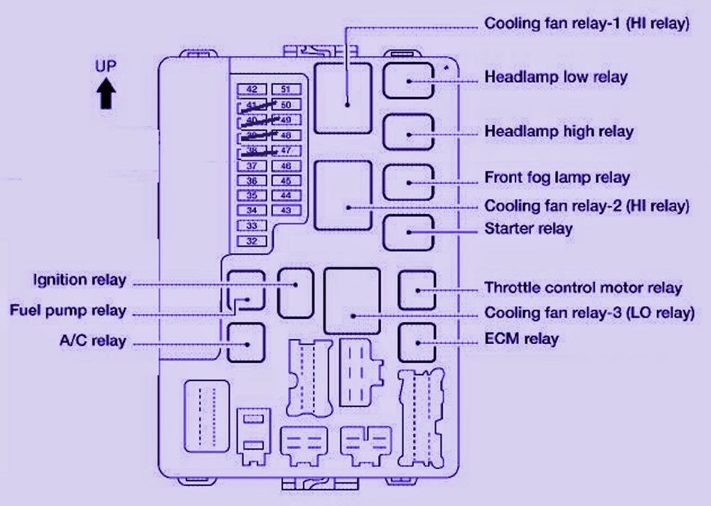
- The Engine Compartment Fuse/Relay Box: Found under the hood, usually near the battery. This box protects circuits related to the engine, such as the fuel pump, ignition system, cooling fan, and headlights.
Each fuse box contains a collection of fuses and, in some cases, relays. A fuse is a safety device containing a thin wire designed to melt and break the circuit if the current exceeds a safe level. This prevents damage to the components wired into the circuit. A relay is an electrically operated switch that allows a low-current circuit to control a high-current circuit. This is often used for components like headlights or the starter motor that require a lot of power.
The fuse diagram itself will typically indicate the following for each fuse:
- Fuse Number/Location: A unique identifier for each fuse, allowing you to pinpoint its position within the fuse box.
- Amperage Rating: The maximum current (measured in amps) that the fuse can handle before blowing. Common ratings include 5A, 7.5A, 10A, 15A, 20A, 25A, and 30A.
- Circuit Protected: A brief description of the component or system that the fuse protects (e.g., "Headlight (RH)", "Radio", "Power Windows").
Understanding Symbols, Lines and Colors
Fuse box diagrams, while generally straightforward, employ a specific visual language. Here's a breakdown:
- Lines: Lines represent electrical wires or conductive pathways. The thickness of a line doesn't necessarily correlate to wire gauge in a fuse diagram. It's primarily there for visual clarity.
- Fuse Symbol: The symbol for a fuse is typically a squiggly line within a rectangular box or a simplified representation of a fuse.
- Relay Symbol: A relay is usually depicted as a coil with a switch. The coil represents the electromagnet that controls the switch.
- Colors: Most aftermarket diagrams do not include color codes. It is critical to note any color coding from original diagrams for advanced troubleshooting with wire harness inspection.
How It Works
The electrical system in your 2003 Altima operates on a 12-volt DC (Direct Current) system. The battery provides the initial power, and the alternator recharges the battery while the engine is running. The fuse box acts as a central distribution point for electrical power. Power flows from the battery, through the fuse box, and then to various components throughout the car. Each component is protected by a fuse with an appropriate amperage rating. If a fault occurs in a circuit, such as a short circuit (a direct path to ground), the current will spike. This excessive current will cause the fuse to blow, interrupting the circuit and preventing further damage.
Relays are used to control high-current circuits with low-current signals. For example, when you turn on your headlights, you're actually activating a relay. The headlight switch sends a small electrical signal to the relay's coil, which then closes the high-current circuit that powers the headlights.
Real-World Use: Basic Troubleshooting Tips
Let's say your radio stops working. Here's how to use the fuse box diagram to troubleshoot:
- Consult the Diagram: Locate the diagram (download is available at the end of this article.) and identify the fuse associated with the radio. It might be labeled "Radio", "Audio", or something similar.
- Locate the Fuse: Go to the interior fuse box (under the dashboard) and find the fuse that corresponds to the diagram.
- Inspect the Fuse: Visually inspect the fuse. A blown fuse will typically have a broken filament (the thin wire inside the fuse). You can also use a multimeter to test the fuse for continuity (a complete circuit).
- Replace the Fuse: If the fuse is blown, replace it with a new fuse of the same amperage rating. Never use a fuse with a higher amperage rating, as this could damage the circuit.
- Test the System: Turn on the radio to see if it now works. If it does, you've solved the problem. If the fuse blows again immediately, there's likely a short circuit in the radio's wiring.
Safety Considerations
Working with automotive electrical systems can be dangerous if you're not careful. Here are some key safety precautions:
- Disconnect the Battery: Before working on any electrical components, disconnect the negative (-) terminal of the battery. This will prevent accidental shorts and shocks.
- Use the Right Tools: Use insulated tools designed for automotive electrical work.
- Never Bypass a Fuse: Never replace a fuse with a piece of wire or other conductive material. This can create a fire hazard.
- Be Careful with Airbags: Airbags are electrically activated and can deploy unexpectedly if mishandled. If you're working near airbags, consult a service manual for specific safety instructions.
- Identify High-Current Circuits: Be particularly cautious when working with high-current circuits like the starter motor, alternator, and headlights. These circuits can deliver a powerful shock.
The circuits related to the fuel pump and airbags should be handled with utmost care. Improper handling can lead to fuel leaks and accidental airbag deployment, both presenting significant safety risks.
This guide offers a comprehensive overview of the 2003 Nissan Altima fuse box diagram. With this knowledge, you'll be better equipped to troubleshoot electrical problems, perform safe modifications, and gain a deeper understanding of your vehicle's electrical system. Always consult the official service manual for specific procedures and warnings.
We have a high-resolution copy of the 2003 Nissan Altima Fuse Box Diagram available for download. Please click [link to download].