
2003 Nissan Frontier Vacuum Hose Diagram
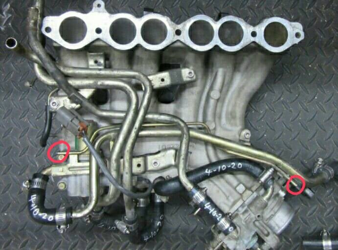
Welcome, fellow gearheads! Today, we’re diving deep into the often-overlooked but incredibly important world of vacuum hoses on your 2003 Nissan Frontier. This guide will break down the vacuum hose diagram, helping you understand its role, interpret its symbols, and ultimately use it for diagnostics and repairs. Whether you're chasing down a pesky engine code, performing routine maintenance, or even tackling a minor modification, understanding your vacuum system is crucial.
Purpose of the 2003 Nissan Frontier Vacuum Hose Diagram
Why bother with a vacuum hose diagram? Simple: it's the roadmap of your engine's vacuum system. The vacuum system is responsible for a surprising number of functions, from controlling emissions to assisting with braking and managing fuel efficiency. A leak or blockage in this system can lead to a whole host of problems, including:
- Poor engine performance (rough idle, hesitation, stalling)
- Reduced fuel economy
- Illuminated check engine light (CEL) with codes related to lean conditions, EGR flow, or EVAP system faults
- Brake issues (reduced power assist)
- Problems with HVAC functions (heater/AC blend door operation)
The diagram provides a visual representation of all the vacuum lines, their connections to various components, and their routing throughout the engine bay. This allows you to:
- Identify individual hoses and their corresponding components.
- Trace vacuum lines to pinpoint leaks or blockages.
- Verify correct hose routing after repairs or modifications.
- Understand the overall function of the vacuum system.
Key Specs and Main Parts of the Vacuum System
The 2003 Nissan Frontier utilizes a vacuum system that incorporates several key components, each playing a specific role. The 2.4L KA24DE and the 3.3L VG33E engines both rely heavily on vacuum for proper operation, although the specific routing and component placement can differ slightly between the two. We’ll focus on the general principles that apply to both engines. The main parts typically include:
- Intake Manifold: This is the primary source of vacuum for the system. Vacuum is created here due to the piston moving downward on the intake stroke while the throttle plate is closed.
- Vacuum Reservoir: A storage tank that maintains a consistent vacuum level, especially important when engine vacuum fluctuates.
- Check Valves: These one-way valves prevent vacuum from bleeding off in certain parts of the system.
- EGR Valve (Exhaust Gas Recirculation): Uses vacuum to open the valve, allowing exhaust gases to be recirculated back into the intake, reducing NOx emissions.
- EVAP System (Evaporative Emission Control): Uses vacuum to purge fuel vapors from the charcoal canister, preventing them from being released into the atmosphere. This includes components such as the Purge Control Valve (PCV) and the Canister Vent Control Valve.
- PCV Valve (Positive Crankcase Ventilation): Regulates the flow of crankcase gases back into the intake manifold for combustion.
- Brake Booster: Uses engine vacuum to assist the driver in applying the brakes, reducing the amount of force required on the brake pedal.
- HVAC System: Vacuum actuators control the blend doors that direct airflow within the cabin.
- Throttle Body: This component controls the amount of air entering the engine, and it often has vacuum ports for various accessories.
The *diameter* of the vacuum hoses is also a crucial spec. Using the wrong size hose can lead to leaks or improper connections. Most hoses are typically 3/16" or 1/4" inside diameter, but it's always best to refer to the diagram or the original hose for the correct size.
Understanding Symbols in the Vacuum Hose Diagram
Vacuum hose diagrams aren't just pictures of hoses; they use a set of symbols to convey information about the components and their connections. Here's a breakdown of the common symbols you'll encounter:
- Solid Lines: Typically represent vacuum hoses. The thickness of the line might indicate the hose diameter.
- Dashed Lines: Often represent control signals or electrical connections related to vacuum-operated devices.
- Arrows: Indicate the direction of vacuum flow. This is especially important for understanding the function of check valves.
- Circles or Rectangles: Represent vacuum-operated components like valves, actuators, and solenoids. They may be labeled with abbreviations (e.g., EGR, PCV, EVAP).
- "T" or "Y" Connectors: Show where vacuum lines split or join.
- Color Coding: Some diagrams use color-coded lines to differentiate between different vacuum circuits. However, the color coding can vary depending on the specific diagram, so always refer to the legend. Common colors include black, red, green, and blue.
Important Note: Diagrams often use abbreviations. Familiarize yourself with common automotive abbreviations to quickly identify components (e.g., MAP - Manifold Absolute Pressure sensor, IAC - Idle Air Control valve).
How the Vacuum System Works
At its core, the vacuum system relies on the pressure difference between the atmosphere and the vacuum created within the engine's intake manifold. This pressure difference is harnessed to operate various components. For example, the EGR valve opens when exposed to vacuum, allowing exhaust gases to flow into the intake manifold. The EVAP system uses vacuum to draw fuel vapors from the charcoal canister and burn them in the engine. The brake booster uses vacuum to amplify the force applied to the brake pedal. A check valve ensures that vacuum is only applied to the desired system at the correct time.
Vacuum leaks disrupt this carefully balanced system. When unmetered air enters the engine through a leak, it throws off the air-fuel ratio, leading to performance problems and potentially damaging the catalytic converter. Furthermore, lost vacuum results in less brake assist or issues with the HVAC controls.
Real-World Use: Basic Troubleshooting Tips
Here are some practical troubleshooting tips using the vacuum hose diagram:
- Visual Inspection: Start by visually inspecting all vacuum hoses for cracks, breaks, or disconnections. Pay close attention to areas where hoses connect to components, as these are common points for leaks. Use the diagram to verify that all hoses are connected to the correct ports.
- Vacuum Gauge Testing: A vacuum gauge can be used to measure the vacuum level at the intake manifold. A low or fluctuating reading can indicate a vacuum leak. Refer to the manufacturer's specifications for the correct vacuum reading for your engine.
- Smoke Testing: A smoke machine is a valuable tool for finding vacuum leaks. It introduces a visible smoke into the vacuum system, allowing you to easily identify the source of the leak.
- Component Testing: Use a vacuum pump to test the operation of individual vacuum-operated components, such as the EGR valve or brake booster. Apply vacuum to the component and observe its behavior. Refer to the service manual for specific testing procedures.
- Using the Diagram to Isolate the Problem: If you have a specific symptom (e.g., EGR code), use the diagram to trace the vacuum lines related to the EGR system. This will help you narrow down the possible causes of the problem.
Safety Considerations
While working on the vacuum system is generally safe, there are a few precautions to keep in mind:
- Hot Engine Components: Be careful when working around hot engine components, such as the exhaust manifold. Allow the engine to cool down before starting any work.
- Fuel Lines: Be mindful of fuel lines when working near the fuel system. Avoid creating sparks or open flames.
- Battery Disconnect: It’s always a good idea to disconnect the negative battery terminal before starting any electrical work or working on the engine bay, especially when working on or near sensors connected to the vacuum system. This prevents accidental shorts.
- Proper Tools: Use the correct tools for the job to avoid damaging components. Use hose removal pliers designed specifically for vacuum lines.
The brake booster is one component that requires extra care. A leak in the brake booster can significantly reduce braking performance, creating a safety hazard. Always inspect the brake booster carefully for signs of damage or leaks, and replace it if necessary.
Don't underestimate the power of a well-maintained vacuum system. By understanding how it works and using the vacuum hose diagram as your guide, you can keep your 2003 Nissan Frontier running smoothly and efficiently for years to come.
To further aid your repair process, we have a high-resolution version of the 2003 Nissan Frontier vacuum hose diagram available for download. It covers both the 2.4L and 3.3L engines and provides detailed illustrations of hose routing and component locations. Contact us for information on how to access it.