2003 Silverado Ignition Switch Wiring Diagram
If you're tackling electrical issues in a 2003 Chevrolet Silverado, understanding the ignition switch wiring is absolutely crucial. Whether you're dealing with a no-start condition, intermittent electrical glitches, or just want to upgrade your truck with new accessories, knowing your way around this part of the electrical system can save you time, money, and frustration. This article provides a detailed look at the 2003 Silverado ignition switch wiring diagram, explaining its purpose, components, function, and how to use it for troubleshooting.
Purpose of the Ignition Switch Wiring Diagram
The ignition switch wiring diagram serves as a roadmap to the electrical connections of the ignition switch. It's not just a pretty picture; it's a vital tool for:
- Diagnosis and Repair: Pinpointing shorts, opens, and other electrical faults within the ignition circuit.
- Component Testing: Identifying which wires to test for voltage and continuity.
- Security System Integration: Understanding how the ignition system interacts with the vehicle's anti-theft features.
- Accessory Installation: Safely tapping into appropriate power sources for aftermarket accessories like remote starters or alarms.
- Learning: Gaining a deeper understanding of how the Silverado's electrical system functions.
Key Specs and Main Parts
The 2003 Silverado ignition switch isn't just a simple on/off switch. It's a multi-position switch that controls various circuits depending on its position. Here are the main components and specifications to keep in mind:
- Ignition Switch Assembly: The mechanical switch itself, typically located on the steering column. It has several positions: LOCK, ACC (Accessory), ON (Run), and START.
- Wiring Harness Connector: The connector that plugs into the ignition switch assembly. This is where all the wires connect.
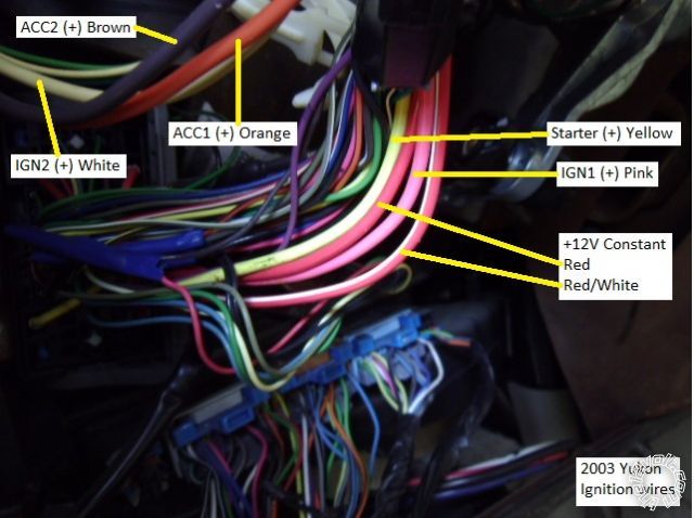
- Battery Feed (B+): A heavy-gauge wire supplying constant power from the battery. This is often a red or orange wire.
- Ignition Feed (IGN): A wire that provides power to the ignition system (coil, distributor, etc.) when the switch is in the ON or START position. Typically a pink wire.
- Accessory Feed (ACC): A wire that provides power to accessories like the radio, wipers, and heater fan when the switch is in the ACC or ON position. Usually an orange or brown wire.
- Starter Solenoid Feed (STRT): A wire that sends power to the starter solenoid when the switch is in the START position. This engages the starter motor to crank the engine. Usually a yellow wire.
- Ground (GND): A wire providing a ground connection for the switch or associated circuits. Often a black wire. While the ignition switch itself might not have a direct ground wire, understanding nearby ground points is vital.
Understanding the *gauge* of the wires is also essential. B+ wires are generally thicker (lower gauge number) because they carry higher amperage. Using the correct gauge wire when making repairs or modifications is critical for safety and preventing voltage drops.
Understanding the Wiring Diagram: Symbols, Lines, and Colors
Deciphering a wiring diagram requires understanding the common symbols and conventions used. Here's a breakdown:
- Lines: Solid lines represent wires. Dashed lines may indicate shielded wires or connections within a module.
- Colors: Wire colors are typically abbreviated (e.g., RED, BLK, YEL, GRN, BLU). A stripe color may be indicated as well (e.g., RED/WHT means a red wire with a white stripe). Color coding helps identify wires quickly.
- Symbols:
- Circle with a Cross: Represents a wire splice (where multiple wires connect).
- Rectangle: Often represents a connector.
- Coil Symbol: Indicates a relay or solenoid.
- Ground Symbol (typically three horizontal lines decreasing in size): Indicates a connection to the vehicle's chassis ground.
- Component Labels: Each component (e.g., ignition switch, starter relay) is labeled with a name or abbreviation.
- Pin Numbers: The diagram should clearly show the pin numbers on the ignition switch connector. This is crucial for identifying the correct wires to test or connect to.
The diagram also shows the pathway of current flow. Follow the lines to trace how power flows from the battery, through the ignition switch, and to the various circuits it controls.
How the Ignition Switch Works
The ignition switch's primary function is to selectively connect and disconnect various electrical circuits based on its position. Here's a simplified explanation of how it works:
- LOCK: In this position, the steering wheel is locked, and no electrical circuits are energized (except perhaps a courtesy light circuit). The key can be inserted and removed.
- ACC (Accessory): In this position, power is supplied to accessories like the radio, power windows, and wipers, but the ignition system is not active. This allows you to use these features without running the engine.
- ON (Run): This is the normal operating position. Power is supplied to the ignition system (coil, distributor, fuel pump), the engine control module (ECM), and all accessories. The engine is running, and all vehicle systems are functioning.
- START: In this position, power is supplied to the starter solenoid, which engages the starter motor to crank the engine. Once the engine starts, you release the key, and the switch springs back to the ON position. The starter circuit is usually *disabled* once the engine is running to prevent accidental re-engagement of the starter.
Internally, the ignition switch uses a series of contacts that make and break connections as the switch is rotated. A worn or faulty switch can have damaged contacts, preventing the correct circuits from being energized.
Real-World Use: Basic Troubleshooting Tips
Here are some basic troubleshooting steps you can take using the ignition switch wiring diagram:
- No-Start Condition: Check the battery voltage first. If the battery is good, use a multimeter to test for voltage at the B+ wire of the ignition switch connector. If there's no voltage there, the problem is upstream (e.g., a blown fuse, a broken wire).
- No Power to Accessories: Check the ACC wire for voltage in the ACC and ON positions. If there's no voltage, the switch might be faulty, or the ACC wire might be broken.
- Engine Cranks But Won't Start: Check the IGN wire for voltage in the ON and START positions. If there's no voltage, the ignition system isn't getting power. The switch could be faulty, or there may be an issue with the ignition fuse or wiring.
- Starter Stays Engaged: This is a dangerous condition. Immediately disconnect the battery. The starter solenoid or the ignition switch itself could be faulty. Do not attempt to drive the vehicle until this is resolved.
Always use a multimeter to test for voltage and continuity. A test light can be used for basic voltage checks, but a multimeter provides more accurate readings and can measure resistance.
Safety Considerations
Working with automotive electrical systems can be dangerous. Here are some safety precautions:
- Disconnect the Battery: Always disconnect the negative battery terminal before working on any electrical component. This prevents accidental shorts and electrical shocks.
- Airbag System: Be extremely careful when working near the steering column, as this is where the airbag module is located. Accidental deployment of the airbag can cause serious injury. It's best to consult the vehicle's service manual for the proper procedure for disabling the airbag system before working in this area.
- Fuses: Always replace blown fuses with fuses of the same amperage rating. Using a higher amperage fuse can overload the circuit and cause a fire.
- Wiring: Use proper crimping tools and connectors when making wiring repairs. A loose or corroded connection can cause electrical problems and even a fire.
- Avoid Grounding: Be careful not to ground any live wires accidentally. This can cause a short circuit and damage the electrical system.
Remember, if you're not comfortable working with electrical systems, it's best to consult a qualified mechanic.
We have a copy of the 2003 Silverado Ignition Switch Wiring Diagram available for download. It is a valuable resource for any DIY mechanic working on this vehicle.