2003 Toyota Sequoia Fuse Box Diagram
Alright, let's dive into the 2003 Toyota Sequoia fuse box diagram. This isn't just a map; it's your key to understanding, diagnosing, and potentially fixing electrical gremlins in your Sequoia. Whether you're tackling a blown fuse, installing aftermarket accessories, or simply want to understand your truck's electrical system better, having a solid grasp of this diagram is crucial.
Purpose: Why Bother with a Fuse Box Diagram?
Why should you care about a seemingly complex schematic? The primary reasons are:
- Troubleshooting Electrical Issues: A blown fuse is often the first sign of an electrical problem. The diagram identifies which fuse protects which circuit (e.g., headlights, power windows, radio). This saves you from replacing every fuse in the box.
- Installing Aftermarket Accessories: Adding things like aftermarket lights, a new sound system, or a trailer brake controller requires tapping into the vehicle's electrical system. Knowing the fuse layout helps you choose the right circuit and install a fuse tap safely.
- Understanding Your Vehicle: Even if you're not actively working on your Sequoia, understanding the fuse box diagram provides valuable insight into how its electrical system is organized. This empowers you to better diagnose potential issues and communicate effectively with a mechanic.
- Preventing Major Damage: Installing the wrong fuse can overload a circuit and potentially cause wiring damage or even a fire. Using the correct diagram ensures you're using the specified amperage for each circuit.
Key Specs and Main Parts of the 2003 Sequoia Fuse System
The 2003 Sequoia typically has two main fuse boxes:
- Interior Fuse Box: Located under the dashboard, often on the driver's side. This box primarily controls circuits related to interior components, such as the instrument panel, power windows, radio, and climate control.
- Engine Compartment Fuse Box: Situated in the engine bay, near the battery. This box manages circuits for critical engine and drivetrain components, including the fuel pump, ignition system, headlights, and anti-lock braking system (ABS).
Inside each box, you'll find:
- Fuses: The sacrificial element in the circuit. They're designed to blow (break the circuit) when excessive current flows through them, preventing damage to other components. Fuses are rated in amps (A), indicating the maximum current they can handle.
- Relays: Electrically operated switches that allow a low-current circuit to control a high-current circuit. For example, the headlight relay allows the headlight switch (which handles a small amount of current) to control the high-current circuit powering the headlights.
- Circuit Breakers: Similar to fuses, but resettable. They automatically interrupt the circuit when overloaded and can be manually reset once the overload is removed. While less common than fuses in these applications, some circuits may use them.
- Fuse Puller: A small plastic tool designed to safely remove and install fuses without damaging them or the fuse box.
Decoding the Symbols, Lines, and Colors
The fuse box diagram uses a standardized set of symbols and conventions. Here’s a breakdown:
- Lines: Solid lines represent electrical wiring. Thicker lines may indicate heavier gauge wiring, capable of handling higher currents.
- Colors: Wires are color-coded to help identify them within the wiring harness. The diagram will usually include a color code chart. Common colors include red (power), black (ground), and various colors for signal and control wires.
- Fuse Symbols: Fuses are typically represented by a stylized line that breaks in the middle, resembling a fuse element. The amperage rating is usually printed next to the symbol (e.g., "15A").
- Relay Symbols: Relays are depicted as a coil and a switch. The coil represents the electromagnet that actuates the switch. The switch shows the normally open (NO) or normally closed (NC) state of the relay contacts.
- Component Symbols: Other components, such as lights, motors, and sensors, are represented by standardized symbols. A legend will define what each symbol represents.
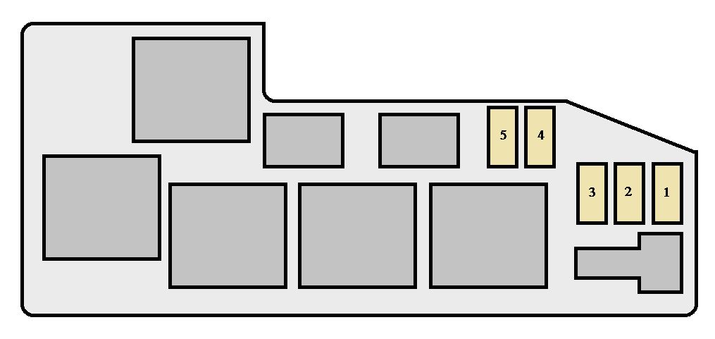
- Numerical Designations: Each fuse and relay location is usually assigned a numerical or alphanumeric designation (e.g., "F12" or "R3"). This corresponds to the marking on the fuse box itself.
The diagram will typically be organized with the fuse locations arranged in the same order as they appear in the physical fuse box. This makes it easier to locate the correct fuse.
How It Works: The Electrical Flow
Understanding how electricity flows through the circuits protected by the fuse box is key to troubleshooting. The basic principle is that electricity flows from the battery, through the ignition switch (when the vehicle is turned on), to the various circuits in the vehicle. Each circuit is protected by a fuse.
If a component draws excessive current (e.g., due to a short circuit), the fuse will blow, interrupting the flow of electricity and preventing damage to the wiring and components in that circuit. The fuse blows because the excessive current generates heat, which melts the fuse element, breaking the circuit.
Relays act as intermediaries in many circuits. A low-current signal from a switch (e.g., the headlight switch) activates the relay, which then closes a high-current circuit to power the component (e.g., the headlights). This allows a small switch to control a powerful electrical device.
Real-World Use: Basic Troubleshooting Tips
Here's how to use the fuse box diagram to troubleshoot common electrical problems:
- Identifying a Blown Fuse: If a component isn't working, check its corresponding fuse. Use the diagram to locate the fuse for that component. Visually inspect the fuse. A blown fuse will typically have a broken filament inside. You can also use a multimeter to test for continuity across the fuse.
- Replacing a Blown Fuse: Always replace a blown fuse with one of the same amperage rating. Using a higher amperage fuse can overload the circuit and cause damage.
- Tracing a Short Circuit: If a fuse blows repeatedly, there's likely a short circuit in the wiring or the component itself. Use the diagram to trace the wiring for that circuit and look for any signs of damage, such as frayed wires or corroded connections.
- Adding an Accessory: When adding an accessory, determine the amperage draw of the accessory and select a fuse tap that can handle that current. Use the diagram to identify a suitable circuit to tap into. Make sure the chosen circuit is not critical to the vehicle's operation (e.g., avoid tapping into the fuel pump circuit).
Safety: Working with Electrical Components
Working with automotive electrical systems can be dangerous. Here are some crucial safety precautions:
- Disconnect the Battery: Before working on any electrical system, disconnect the negative (–) terminal of the battery. This prevents accidental short circuits and electrical shocks.
- Use Insulated Tools: Use tools with insulated handles to protect yourself from electrical shock.
- Avoid Working in Wet Conditions: Water can conduct electricity, increasing the risk of shock.
- Be Careful with High-Current Circuits: Circuits that power components like the starter motor, alternator, and headlights carry high currents. Exercise extra caution when working with these circuits.
- Never Bypass a Fuse: Bypassing a fuse can overload the circuit and cause a fire.
- Be Aware of Airbag Systems: Disconnecting or interfering with airbag system wiring can cause the airbags to deploy accidentally. Consult a professional if you need to work on or near the airbag system.
The 2003 Sequoia’s electrical system includes sensitive components like the Engine Control Unit (ECU) and ABS module. Incorrect fuse replacement or wiring modifications near these systems can cause significant damage. If you're unsure about any aspect of the electrical system, it's always best to consult a qualified mechanic.
You now have a solid understanding of the 2003 Toyota Sequoia fuse box diagram. We have a downloadable file containing the complete diagram with all the specifications and details mentioned above, contact us for a copy.