2004 Chevrolet Trailblazer Fuse Box Diagram
Alright, let's dive into the fuse box diagram for the 2004 Chevrolet Trailblazer. This guide is tailored for those of you who are comfortable working on your vehicles and want to understand the electrical system a bit better. Whether you're troubleshooting a faulty component, planning some modifications, or simply want to know where everything is, this information is invaluable.
Purpose of the Fuse Box Diagram
Why bother with a fuse box diagram? Simple: it's the roadmap to your Trailblazer's electrical nervous system. The diagram serves several crucial purposes:
- Troubleshooting Electrical Issues: When something electrical stops working (e.g., a light, the radio, the A/C), the first place to check is often the fuses. The diagram helps you locate the fuse associated with that specific circuit.
- Identifying Circuit Function: The diagram clearly labels each fuse and relay, telling you exactly what it protects and controls. This is essential for understanding how the electrical system is laid out.
- Planning Modifications: If you're adding aftermarket accessories (e.g., lights, a sound system), you need to know where you can safely tap into the electrical system. The diagram helps you find suitable power sources and avoid overloading circuits.
- Preventing Electrical Fires: Fuses are designed to protect circuits from overcurrents. A blown fuse indicates a potential problem. Replacing a blown fuse with one of a higher amperage is extremely dangerous and can lead to an electrical fire. The diagram ensures you use the correct fuse rating.
Key Specs and Main Parts
The 2004 Trailblazer typically has two main fuse box locations:
- Underhood Fuse Box: Located in the engine compartment, usually on the driver's side. This box houses fuses and relays for critical systems like the engine, transmission, headlights, ABS, and cooling fans. It's the primary distribution point for high-current circuits.
- Rear Fuse Box (Under Rear Seat): Located under the rear seat. This box controls less critical systems like the rear wiper, the rear window defogger, the rear audio.
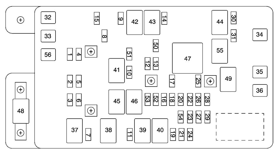
The diagram itself is a schematic representation of these boxes. Key components you'll find on the diagram include:
- Fuses: These are the sacrificial elements in the circuit, designed to blow and interrupt the current flow if it exceeds a safe level. Fuses are rated in amperes (amps), which indicates the maximum current they can handle before blowing. Common fuse types used in the Trailblazer include blade fuses (ATO/ATC), mini blade fuses, and cartridge fuses.
- Relays: These are electrically operated switches that allow a low-current circuit to control a high-current circuit. For example, the headlight relay uses a small current from the headlight switch to switch on a much larger current to power the headlights. Relays are usually labeled with their function (e.g., "Headlight Relay," "Fuel Pump Relay").
- Circuit Breakers: These are similar to fuses but are resettable. They trip and interrupt the circuit when an overcurrent occurs, but they can be reset once the fault is corrected. The Trailblazer uses very few circuit breakers.
- Jumpers/Links: These are solid conductive links used to connect different circuits together.
Understanding the Symbols
The fuse box diagram uses a variety of symbols to represent different components and connections. Understanding these symbols is crucial for interpreting the diagram correctly.
- Lines: Lines represent wires and electrical connections. A solid line indicates a direct connection, while a dashed line may indicate a shielded or ground connection. The thickness of the lines generally doesn't indicate wire gauge on these diagrams, but the context can.
- Fuse Symbol: The typical fuse symbol is a rectangle with a squiggly line running through it. It might be a simple horizontal line with a break in it. The amperage rating is usually indicated next to the symbol.
- Relay Symbol: The relay symbol typically includes a coil (a looped wire) and a switch. The coil represents the electromagnet that activates the switch. The switch represents the contacts that open or close to control the high-current circuit.
- Ground Symbol: The ground symbol indicates a connection to the vehicle's chassis, which serves as the common ground point for the electrical system. This is often represented by a series of horizontal lines getting progressively shorter, resembling an upside-down Christmas tree.
- Color Codes: Wiring diagrams often use color codes to identify individual wires. While not explicitly on the fuse box diagram itself, understanding the GM wire color codes is essential. For example, a wire labeled "RED" would typically be red. A wire labeled "DK BLU/WHT" would be dark blue with a white stripe.
How It Works
The fuse box acts as a central distribution point for electrical power in the vehicle. Power from the battery flows through the main power cables to the fuse box. Within the fuse box, the power is distributed to various circuits, each protected by a fuse or relay. When you turn on a switch (e.g., the headlight switch), you're completing a circuit, allowing current to flow from the battery, through the switch, through the fuse, to the component (e.g., the headlight bulb), and back to ground.
If there's a short circuit or an overcurrent in the circuit, the fuse will blow. This interrupts the current flow, preventing damage to the component and potentially preventing a fire. The fuse is designed to be the weakest link in the circuit, sacrificing itself to protect the rest of the system.
Relays are used to control high-current circuits with low-current switches. The low-current switch activates the relay's coil, which closes the relay's contacts, allowing the high current to flow to the component.
Real-World Use: Basic Troubleshooting Tips
Here's how to use the fuse box diagram to troubleshoot common electrical problems:
- Identify the Problem: Determine which component is not working (e.g., the power windows, the cigarette lighter).
- Consult the Diagram: Locate the fuse associated with the non-working component on the fuse box diagram. Make sure you are looking at the correct diagram, either the underhood or under rear seat.
- Inspect the Fuse: Physically examine the fuse. If the thin wire inside the fuse is broken or blackened, the fuse is blown.
- Replace the Fuse: Replace the blown fuse with a new fuse of the same amperage rating. Never use a fuse with a higher amperage rating.
- Test the Component: After replacing the fuse, test the component to see if it's working. If the fuse blows again immediately, there's still a short circuit or overcurrent in the circuit. You'll need to investigate further to find the source of the problem. This may involve checking wiring, connectors, and the component itself.
Sometimes, the fuse may look fine, but still be faulty. A multimeter set to continuity can be used to verify the fuse is good. If there is continuity through the fuse, the multimeter will beep. If there is no continuity, the fuse is blown, even if it doesn't look like it.
Safety Considerations
Working with automotive electrical systems can be dangerous. Here are some safety precautions to keep in mind:
- Disconnect the Battery: Before working on any electrical system, disconnect the negative terminal of the battery. This will prevent accidental short circuits and shocks.
- Avoid Water: Never work on electrical systems in wet or damp conditions.
- Use Proper Tools: Use insulated tools designed for automotive electrical work.
- Don't Exceed Fuse Ratings: Never replace a fuse with one of a higher amperage rating. This can overload the circuit and cause a fire.
- Be Careful with Relays: Relays can get hot when they're operating. Avoid touching them immediately after the engine has been running.
- Airbags: If you are working near the airbag system, be especially careful. Improper handling can cause the airbags to deploy accidentally, which can be dangerous. Refer to your service manual for specific instructions on disabling the airbag system.
Important Note: Some circuits, such as the ABS and airbag systems, are highly sensitive and require specialized knowledge and tools. If you're not comfortable working on these systems, it's best to take your vehicle to a qualified mechanic.
With a good understanding of the fuse box diagram and these safety precautions, you'll be well-equipped to diagnose and repair many common electrical problems in your 2004 Chevrolet Trailblazer. Remember to always consult your vehicle's repair manual for specific instructions and warnings.
Disclaimer: This information is for educational purposes only and should not be considered a substitute for professional advice. Always consult a qualified mechanic for any repairs or modifications to your vehicle.