2004 Chevy Silverado 1500 Radio Wiring Diagram
Understanding your 2004 Chevy Silverado 1500's radio wiring diagram is crucial for a variety of reasons, from diagnosing a malfunctioning sound system to upgrading your head unit or adding aftermarket components like amplifiers and subwoofers. This guide provides a comprehensive overview of the wiring diagram, equipping you with the knowledge to tackle common audio-related issues and modifications with confidence.
Purpose and Importance of the Radio Wiring Diagram
The radio wiring diagram serves as a roadmap to your Silverado's audio system. It's not just a pretty picture; it's the key to:
- Troubleshooting Electrical Problems: Identifying shorts, open circuits, and faulty connections that can cause your radio to malfunction.
- Installing Aftermarket Components: Safely and correctly wiring in new head units, amplifiers, speakers, and other audio accessories. This is essential to avoid damaging your vehicle's electrical system or the new components.
- Performing Repairs: Accurately tracing wires to find the source of a problem, rather than relying on guesswork.
- Understanding Your System: Gaining a deeper understanding of how your vehicle's audio system is wired and how each component interacts.
- Avoiding Costly Mistakes: Incorrect wiring can damage components and potentially create safety hazards. The diagram helps prevent these errors.
Key Specs and Main Parts of the 2004 Silverado 1500 Radio Wiring
The 2004 Silverado 1500 radio system is relatively straightforward. Here are the main components you'll encounter in the wiring diagram:
- Head Unit (Radio): The central control unit for the audio system. It receives power, processes audio signals, and sends them to the speakers.
- Speakers: Typically, there are four speakers (front left, front right, rear left, rear right) in a standard Silverado. Extended cabs and crew cabs may have additional speakers.
- Amplifier (Optional): Some Silverados came equipped with a factory amplifier, often located under the center console or behind the rear seat. If present, the wiring diagram will show its connections.
- Antenna: Receives radio signals.
- Wiring Harnesses: Bundles of wires that connect the various components of the audio system. The diagram shows the color-coding and pin assignments for each wire in these harnesses.
- Grounding Points: Connections to the vehicle's chassis that provide a return path for electrical current. Proper grounding is essential for the system to function correctly.
- Power Source: Typically sourced from the vehicle's battery via a fuse.
Important Note: The presence and location of the amplifier, as well as the specific wiring configuration, can vary depending on the Silverado's trim level and optional equipment. Always refer to the correct diagram for your specific vehicle.
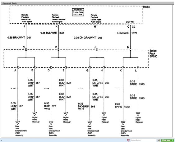
Understanding the Symbols in the Wiring Diagram
Wiring diagrams use a standardized set of symbols to represent different components and connections. Understanding these symbols is essential for interpreting the diagram correctly. Here's a breakdown of the most common symbols you'll encounter:
- Solid Lines: Represent wires. The thickness of the line doesn't usually indicate wire gauge.
- Dashed Lines: May represent shielded cables or connections that are not directly connected to the radio.
- Circles with Numbers: Represent connector pin numbers. These numbers correspond to the pins on the actual connectors in your vehicle.
- Color Codes: Wires are identified by color codes, such as "RED," "BLK," "WHT," "GRN," "BLU," "YEL." These codes are usually abbreviated.
- Ground Symbol: Indicates a connection to the vehicle's chassis ground. It often looks like an inverted triangle or a series of parallel lines.
- Component Symbols: Symbols represent components like resistors, capacitors, diodes, and connectors. A simple rectangle might represent the radio head unit itself.
- Arrows: Sometimes used to indicate the direction of current flow or the path of a signal.
Color codes are especially critical. For example, a wire labeled "RED/WHT" would be a red wire with a white stripe. Knowing these codes allows you to identify the correct wire in a harness. Remember to always double-check with a multimeter for definitive identification before cutting or splicing.
How It Works: Tracing the Signal Path
Let's trace the signal path from the power source to the speakers:
- Power Supply: The radio receives power from the vehicle's battery, typically through a fuse in the fuse box. The diagram will show which fuse is dedicated to the radio. There will be both a constant 12V for memory and a switched 12V that turns on and off with the ignition.
- Ground Connection: The radio requires a solid ground connection to function correctly. This connection is typically made to the vehicle's chassis.
- Head Unit Processing: The head unit receives audio input from various sources (AM/FM radio, CD player, auxiliary input, etc.). It processes these signals and sends them to the speakers or, if equipped, the amplifier.
- Amplification (If Applicable): If the vehicle has a factory amplifier, the head unit sends a low-level signal to the amplifier. The amplifier boosts the signal and sends it to the speakers.
- Speaker Output: The amplified signal (or the head unit's output if there's no separate amplifier) is sent to the speakers via dedicated speaker wires.
The wiring diagram shows the specific wires used for each step in this process. By following the lines and symbols, you can trace the entire signal path and identify potential points of failure.
Real-World Use: Basic Troubleshooting Tips
Here are some common troubleshooting scenarios where the wiring diagram can be invaluable:
- Radio Doesn't Turn On: Check the fuse indicated on the diagram. Use a multimeter to verify that power is reaching the head unit. Inspect the ground connection to ensure it's clean and secure.
- No Sound from One or More Speakers: Use the diagram to trace the speaker wires from the head unit (or amplifier) to the affected speaker. Check for loose connections or damaged wires. Use a multimeter to test for continuity in the speaker wire.
- Static or Interference: Check the antenna connection to ensure it's secure. Inspect the wiring harness for any signs of damage or corrosion. Grounding issues can also cause static, so verify the ground connections.
- Aftermarket Component Installation: When installing a new head unit, carefully match the wires from the new head unit to the corresponding wires in the vehicle's wiring harness, using the diagram as a guide. Use proper wiring connectors and avoid simply twisting wires together.
Always disconnect the negative terminal of the battery before working on the electrical system to prevent short circuits and potential damage.
Safety Precautions
Working with automotive electrical systems can be dangerous. Here are some crucial safety precautions:
- Disconnect the Battery: As mentioned above, always disconnect the negative terminal of the battery before working on any electrical components. This prevents accidental short circuits.
- Use Proper Tools: Use insulated tools specifically designed for automotive electrical work.
- Work in a Well-Lit Area: Good lighting is essential for seeing what you're doing and avoiding mistakes.
- Avoid Water: Never work on electrical systems in wet or damp conditions.
- Identify Wires Carefully: Use the wiring diagram and a multimeter to positively identify wires before cutting or splicing them. Incorrect wiring can damage components and potentially create a fire hazard.
- Be Aware of Airbag Systems: The Silverado's airbag system has its own wiring. Avoid tampering with these wires, as accidental activation of an airbag can cause serious injury. If you're unsure, consult a professional.
Warning: The radio system is connected to the vehicle's electrical system, which includes high-current circuits. Incorrect wiring can result in electrical shocks, fire, and damage to your vehicle. If you are not comfortable working with electrical systems, consult a qualified technician.
Final Thoughts
Understanding your 2004 Chevy Silverado 1500's radio wiring diagram is a valuable skill for any DIY enthusiast. By using the diagram as a guide and following proper safety precautions, you can diagnose and repair audio-related issues, install aftermarket components, and gain a deeper understanding of your vehicle's electrical system. Remember to always double-check your work and consult a professional if you're unsure about any aspect of the process.
We have the complete 2004 Chevy Silverado 1500 radio wiring diagram available for download. It provides detailed information on all the wires, connectors, and components in the system. You can use it as a reference tool when working on your Silverado's audio system. It will save you time and possibly money on repairs by being able to identify issues quicker. The information will help ensure you are working with the right wires when doing upgrades or replacement repairs.