2004 Chevy Silverado Front Differential Diagram
For the seasoned DIY mechanic or car enthusiast tackling a 2004 Chevy Silverado, understanding the front differential is paramount. Whether you're diagnosing a noisy axle, planning a gear ratio change, or simply deepening your knowledge of your truck's drivetrain, a good diagram is your best friend. This article dives deep into the 2004 Silverado front differential diagram, providing a clear breakdown of its components, function, and how to use it for effective troubleshooting.
Why This Diagram Matters
A front differential diagram isn't just a pretty picture; it's a roadmap to understanding a critical part of your Silverado's 4x4 system. It's essential for:
- Repairs: Identifying specific components for replacement and understanding their relationships.
- Troubleshooting: Pinpointing the source of noises, vibrations, or performance issues.
- Modifications: Planning gear ratio changes, locker installations, or other upgrades.
- General Understanding: Gaining a deeper knowledge of your vehicle's mechanics.
Attempting any work on your differential without a solid understanding can lead to further damage, incorrect installations, and potentially unsafe conditions. The diagram provides the visual reference you need to proceed confidently.
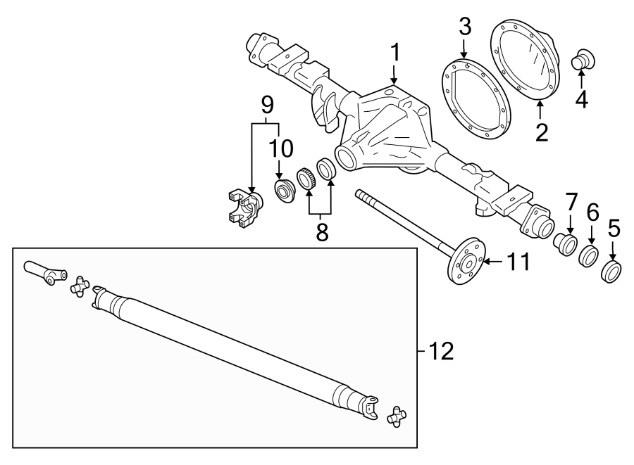
Key Specs and Main Parts
The 2004 Chevy Silverado 1500, particularly those with the 4x4 option, typically used an 8.25" IFS (Independent Front Suspension) differential. Here's a breakdown of the key components you'll find in the diagram:
- Differential Housing: The protective outer shell that contains all the internal components. It's often referred to as the axle housing.
- Ring Gear: A large, circular gear that meshes with the pinion gear. Its size directly influences the gear ratio.
- Pinion Gear: A smaller gear that drives the ring gear, transferring power from the driveshaft.
- Carrier: The rotating housing that supports the spider gears and side gears. It's also sometimes called the differential case.
- Spider Gears (Pinion Gears): Smaller gears within the carrier that allow the wheels to rotate at different speeds during turns.
- Side Gears: Gears splined to the axle shafts, transferring power to the individual wheels.
- Axle Shafts: The rotating shafts that transmit power from the side gears to the wheels.
- Bearings: Support the rotating components, reducing friction and allowing smooth operation (e.g., pinion bearings, carrier bearings).
- Seals: Prevent lubricant leakage and keep contaminants out (e.g., pinion seal, axle seals).
- Shims: Thin washers used to adjust bearing preload and gear mesh for optimal performance and longevity.
- Actuator (4WD Models): Electrically or vacuum-operated mechanism that engages the front differential.
The gear ratio is a critical specification, indicating the number of pinion gear revolutions required to turn the ring gear once. Common ratios for this era Silverado might be 3.42, 3.73, or 4.10. This number significantly impacts acceleration and fuel economy. Knowing your ratio is crucial for selecting compatible parts during repairs or upgrades.
Understanding the Symbols
Deciphering the symbols on a differential diagram is crucial. Here's a breakdown of common conventions:
- Solid Lines: Typically represent solid components, such as gears, shafts, and housings.
- Dashed Lines: Often indicate oil passages or lubricant flow paths.
- Circular Symbols: Usually denote bearings. The type of bearing (e.g., roller, ball) may be indicated by internal markings within the circle.
- Arrows: Show the direction of rotation or force.
- Numbers/Labels: Correspond to a parts list, allowing you to identify specific components.
- Colors: May be used to differentiate between different materials or systems, although this is less common in standard diagrams. Consult the diagram's legend for specific color coding.
Pay close attention to the legend or key that accompanies the diagram. This will explain any unique symbols or notations used in that particular representation.
How It Works
The front differential's primary function is to transmit power from the driveshaft to the front wheels while allowing them to rotate at different speeds during turns. Here's a simplified explanation:
- The driveshaft rotates the pinion gear.
- The pinion gear meshes with and rotates the ring gear.
- The ring gear is bolted to the carrier.
- The carrier houses the spider gears and side gears.
- When the vehicle is traveling straight, the spider gears do not rotate relative to the carrier. They simply transmit power equally to the side gears and, in turn, to the axle shafts and wheels.
- During a turn, the outer wheel needs to travel further than the inner wheel. The spider gears rotate within the carrier, allowing the side gears (and thus the axle shafts) to rotate at different speeds. This prevents wheel slippage and binding.
In 4WD models, an actuator engages the front differential, connecting the front driveshaft to the front axle shafts. This allows the engine to drive both the front and rear wheels, providing increased traction in off-road or slippery conditions. When 4WD is disengaged, the actuator disconnects the front driveshaft, allowing the front wheels to rotate freely without being driven by the engine.
Real-World Use: Basic Troubleshooting Tips
The diagram can be invaluable for diagnosing common front differential problems:
- Whining Noise: Often indicates worn pinion bearings, a bad carrier bearing or improper gear mesh. Use the diagram to locate these components and inspect them for damage.
- Clunking Noise: Could be caused by excessive backlash (play) in the gears, worn spider gears, or a damaged carrier. Refer to the diagram to understand the gear relationships and identify potential sources of looseness.
- Vibration: May be due to an unbalanced driveshaft, a bent axle shaft, or worn U-joints. The diagram helps you trace the rotational components and pinpoint the source of the vibration.
- Fluid Leaks: Check the pinion seal and axle seals. The diagram clearly shows their location and how to access them.
- 4WD Engagement Issues: If the 4WD won't engage, inspect the actuator. The diagram illustrates its location and connection to the differential.
When troubleshooting, always start with a visual inspection. Look for leaks, damage, and loose connections. Then, use the diagram to guide your disassembly and inspection process. Remember to consult your Silverado's service manual for detailed diagnostic procedures and torque specifications.
Safety Considerations
Working on a differential involves handling heavy components and potentially hazardous substances. Here are some key safety precautions:
- Wear Safety Glasses: Protect your eyes from debris and fluids.
- Use Gloves: Protect your hands from sharp edges and chemicals.
- Support the Vehicle Properly: Use jack stands to securely support the vehicle before working underneath it. Never rely solely on a jack.
- Handle Fluids Carefully: Differential fluid can be messy and may contain contaminants. Dispose of used fluid properly.
- Be Aware of Heavy Components: The differential housing and internal components can be heavy. Use proper lifting techniques or a hoist to avoid injury.
- Secure the Pinion Gear: When removing the pinion nut, properly secure the pinion gear to prevent it from spinning. Improper removal can damage the threads or bearings.
- Work in a Well-Ventilated Area: Some cleaning solvents and lubricants can produce harmful fumes.
The pinion gear and ring gear require precise shimming and installation. Incorrect settings can lead to premature wear and failure. If you're not comfortable with this level of precision, it's best to consult a professional mechanic.
We have a high-resolution version of the 2004 Chevy Silverado Front Differential Diagram available for download. This detailed diagram will be an invaluable resource for your repair or upgrade project. Feel free to reach out if you need the file. Good luck with your project, and remember to prioritize safety!