
2004 Chevy Tahoe Radio Wiring Harness
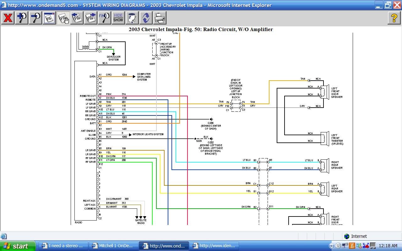
Understanding the 2004 Chevy Tahoe radio wiring harness is crucial for various tasks, from replacing a faulty head unit to installing aftermarket audio equipment. This detailed guide aims to provide experienced DIYers and intermediate car owners with the knowledge needed to navigate this complex system safely and effectively. Whether you're troubleshooting a problem, upgrading your sound system, or simply seeking to understand your vehicle better, this information will prove invaluable. We will discuss the purpose of understanding the wiring harness, key specifications, symbols, how it works, real-world usage, and safety precautions.
Purpose of Understanding the Radio Wiring Harness
The radio wiring harness serves as the central nervous system for your Tahoe's audio system. Understanding its layout and function is essential for several reasons:
- Radio Replacement/Upgrade: Swapping out the factory radio for an aftermarket unit requires correctly identifying and connecting the appropriate wires.
- Speaker Upgrades: Adding amplifiers or new speakers necessitates understanding the existing wiring and impedance (a measure of a circuit's opposition to the flow of alternating current).
- Troubleshooting Audio Issues: Diagnosing problems like no sound, distorted audio, or a non-functional radio often involves tracing the wiring and checking for continuity (a complete and unbroken path for electrical current).
- Adding Accessories: Installing accessories like subwoofers, backup cameras, or hands-free calling systems often requires tapping into specific wires within the harness.
- Understanding Vehicle Electrical System: Working with the radio harness provides a good foundation for understanding the broader electrical system of your vehicle.
Key Specs and Main Parts of the 2004 Tahoe Radio Wiring Harness
The 2004 Chevy Tahoe radio wiring harness is a collection of wires bundled together, each serving a specific function. These wires connect the radio head unit to various components such as the speakers, power source, antenna, and vehicle's computer system. Here's a breakdown of the key components:
- Power Wires:
- Constant 12V (B+): Provides continuous power to the radio for memory functions, even when the ignition is off.
- Switched 12V (ACC): Powers the radio on and off with the ignition switch.
- Ground: Completes the electrical circuit, providing a return path for the current.
- Speaker Wires: Carry the audio signal from the radio to the speakers. Each speaker (front left, front right, rear left, rear right) has a positive (+) and a negative (-) wire.
- Antenna Wire: Connects the radio to the antenna, allowing it to receive radio signals. Typically a coaxial cable.
- Illumination Wire: Dims the radio display when the headlights are turned on.
- Data Wires (if equipped): Some Tahoes have data wires that connect the radio to the vehicle's computer (ECU or ECM). These wires may be used for features like steering wheel controls or displaying vehicle information on the radio screen. These communicate using protocols like CAN bus.
The connector itself is typically a multi-pin connector, designed to plug directly into the back of the factory radio. Aftermarket radio installations often require an adapter harness that plugs into the factory connector and provides standardized wires for the new radio.
Symbols and Conventions Used in Wiring Diagrams
Wiring diagrams use a standardized set of symbols and conventions to represent electrical components and their connections. Understanding these symbols is crucial for interpreting the diagram correctly:
- Lines: Represent wires. Solid lines indicate a direct connection, while dashed lines may indicate a shielded wire or a connection that is only present in certain trim levels.
- Colors: Wires are color-coded to help identify their function. Common colors include red (power), black (ground), yellow (constant 12V), and various other colors for speaker wires and other functions. The color code will be indicated in the wiring diagram.
- Circles: Can represent connectors, splices, or other connection points.
- Squares/Rectangles: Often represent components such as the radio head unit, speakers, or other modules.
- Resistor Symbol (Zig-zag line): Represents a resistor, which limits the flow of current.
- Capacitor Symbol (Two parallel lines): Represents a capacitor, which stores electrical energy.
- Ground Symbol (Series of horizontal lines): Indicates a connection to ground.
The diagram will also include labels indicating the function of each wire, such as "ACC," "GND," "FL+," "FR-," etc. Carefully study the legend or key on the diagram to understand the specific symbols and abbreviations used.
How the Radio Wiring Harness Works
The radio wiring harness acts as a conduit for electrical signals and power, enabling the radio to function and communicate with other vehicle systems. Here's a simplified explanation of how it works:
- Power Supply: The constant 12V wire provides continuous power to the radio, allowing it to retain memory settings (e.g., saved radio stations, clock settings). The switched 12V wire provides power only when the ignition is turned on, activating the radio. The ground wire completes the circuit.
- Signal Reception: The antenna wire connects the radio to the antenna, which receives radio signals. The radio processes these signals and outputs audio.
- Audio Output: The speaker wires carry the amplified audio signal from the radio to the speakers. Each speaker has a positive and a negative wire, which must be connected correctly to ensure proper phasing (the speakers move in and out together, rather than canceling each other out). Incorrect phasing will result in poor bass response.
- Data Communication (if applicable): If the Tahoe is equipped with data wires, the radio can communicate with the vehicle's computer system. This allows for features like steering wheel controls, displaying vehicle information on the radio screen, and integrating the radio with other vehicle systems.
Real-World Use and Basic Troubleshooting Tips
Here are some basic troubleshooting tips for working with the 2004 Chevy Tahoe radio wiring harness:
- No Power to Radio: Check the fuses related to the radio. Use a multimeter to check for voltage on the constant 12V and switched 12V wires. Verify the ground connection is secure and making good contact with the vehicle's chassis.
- No Sound from Speakers: Check the speaker wire connections at the radio and at the speakers. Use a multimeter to check for continuity in the speaker wires. If an amplifier is used, check its power and ground connections. Verify the speaker impedance matches what the radio/amplifier is designed for.
- Distorted Audio: Check the speaker wire connections for shorts to ground. Inspect the speakers for damage. A DC offset test can determine the speaker output health by measuring the DC voltage with a multimeter at each speaker wire while the radio is on but muted. This will diagnose problems with a head unit amplifier.
- Steering Wheel Controls Not Working: Check the data wire connections between the radio and the vehicle's computer. Verify that the radio is programmed to recognize the steering wheel control signals.
- Antenna Problems: Check the antenna connection at the radio and at the antenna base. Inspect the antenna cable for damage. Consider using an antenna signal booster if reception is weak.
Safety Precautions
Working with electrical systems can be dangerous. Always take the following precautions:
- Disconnect the Battery: Before working on any electrical components, disconnect the negative terminal of the battery to prevent accidental shorts or electrical shock.
- Use Proper Tools: Use insulated tools designed for working with electrical systems.
- Avoid Water: Never work on electrical systems in wet or damp conditions.
- Identify Wires Carefully: Double-check wire identifications before making any connections. Refer to the wiring diagram and use a multimeter to verify the correct wires.
- Be Aware of Airbag Systems: The radio wiring harness may be located near airbag system components. Avoid disturbing these components, as accidental deployment can cause serious injury.
- Fuses: Always replace fuses with the correct amperage rating. Using a higher amperage fuse can damage the electrical system.
Remember, if you are not comfortable working with electrical systems, it is always best to consult a qualified professional.
We have a detailed wiring diagram for the 2004 Chevy Tahoe radio wiring harness available for download. This diagram provides a comprehensive overview of the wiring layout and color codes, making it an invaluable resource for your DIY projects.