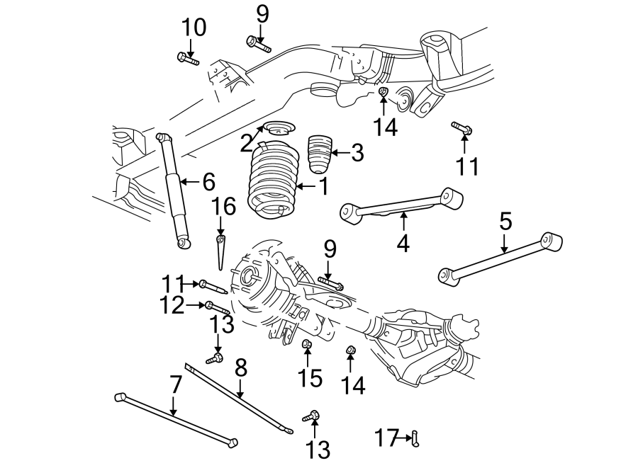
2004 Chevy Trailblazer Rear Suspension Diagram
Let's dive into the rear suspension system of a 2004 Chevy Trailblazer. Understanding this system is crucial whether you're tackling a repair, planning an upgrade, or simply want to learn more about how your vehicle handles. This isn't just about replacing parts; it's about grasping the interplay of components and how they affect ride quality, handling, and safety. We’ll be using a rear suspension diagram as our guide. Knowing where to find and interpret this diagram will save you time and headaches.
Purpose of Understanding the Rear Suspension Diagram
Why bother with a diagram? Because it's the blueprint for your rear suspension. It's invaluable for:
- Troubleshooting: Diagnosing issues like sagging, excessive bouncing, or unusual noises.
- Repairing: Correctly identifying and replacing worn or damaged components.
- Upgrading: Planning suspension modifications, such as adding a lift kit or performance shocks.
- General Knowledge: Simply understanding how your vehicle's rear suspension operates.
A diagram allows you to visually map out the system, understand the relationships between components, and confidently approach repairs or modifications. We have the full diagram available for download.
Key Specs and Main Parts
The 2004 Chevy Trailblazer utilizes a five-link solid rear axle suspension. This design is chosen for its robustness, load-carrying capacity, and relative simplicity. The solid axle means both rear wheels are connected by a single beam, promoting stability, especially in off-road conditions.
Here's a breakdown of the main components:
- Rear Axle Assembly: The core of the system. It houses the differential, axle shafts, and provides the mounting points for other suspension components.
- Coil Springs: Provide the primary support for the vehicle's weight and absorb vertical impacts.
- Shock Absorbers (Dampers): Control the oscillation of the coil springs, preventing excessive bouncing and maintaining tire contact with the road.
- Upper Control Arms (Two): These links help locate the axle and control lateral movement during suspension travel.
- Lower Control Arms (Two): These are typically longer and more robust than the upper control arms, providing significant support and control.
- Track Bar (Panhard Rod): Prevents lateral movement of the axle relative to the vehicle's frame. It's crucial for maintaining stability, especially during cornering.
- Bump Stops: Prevent the suspension from bottoming out, protecting the components from damage during extreme compression.
- Sway Bar (Anti-Roll Bar): Connects the left and right sides of the suspension to reduce body roll during cornering, improving handling.
Understanding the Diagram Symbols
Deciphering a suspension diagram requires understanding the common symbols used. These diagrams are often schematic, meaning they're simplified representations, not literal pictures.
- Lines: Different line types represent different things. Solid lines usually indicate rigid components like control arms or the axle housing. Dashed lines might represent the sway bar or indicate a hidden part.
- Colors: Colors are often used for identification. For example, one color might highlight components that need to be tightened to a specific torque, while another identifies electrical connections (if any, for electronically controlled shocks). Your specific diagram will likely have a key explaining its color coding.
- Icons:
- Circles: Commonly represent pivot points or bushings.
- Rectangles: Might depict mounting brackets or other structural elements.
- Triangles: Sometimes indicate the direction of forces or movement.
- Torque Specifications: Critical numbers indicating the correct tightness for fasteners. Exceeding these values can damage threads; under-tightening can lead to component failure. These are usually listed near the relevant fastener on the diagram.
Always refer to the diagram's legend or key to understand the specific symbols used.
How the Rear Suspension Works
The rear suspension's primary function is to isolate the vehicle's body from road imperfections, providing a comfortable ride and maintaining tire contact for optimal handling. Let's break down the process:
- Impact Absorption: When the wheels encounter a bump, the coil springs compress, absorbing the energy of the impact.
- Dampening Oscillation: The shock absorbers then control the release of that energy, preventing the springs from bouncing excessively. They do this by forcing hydraulic fluid through small orifices, converting kinetic energy into heat.
- Axle Location: The upper and lower control arms work together to locate the axle assembly, preventing it from moving excessively forward, backward, or sideways.
- Lateral Stability: The track bar prevents the axle from shifting laterally, maintaining proper alignment and preventing "crab walking."
- Roll Control: The sway bar connects the left and right sides of the suspension. When the vehicle leans during a turn, the sway bar twists, transferring some of the force from the compressed side to the extended side, reducing body roll.
The five-link design allows for a good balance of ride comfort, handling, and load-carrying capacity. The separate control arms and track bar allow for more precise control over axle movement compared to simpler designs.
Real-World Use: Basic Troubleshooting
Here are a few common problems and how the diagram can help:
- Sagging Rear End: Could indicate worn-out coil springs. The diagram helps you locate the spring and understand its relationship to other components for removal and replacement.
- Excessive Bouncing: Likely a sign of worn shock absorbers. The diagram shows you where the shocks are mounted and how they connect.
- Clunking Noises: Often caused by worn bushings in the control arms or track bar. The diagram allows you to identify each bushing and its location for inspection.
- Rear End "Wander" or Instability: Could be a sign of a loose track bar or worn track bar bushings. The diagram clearly shows the track bar's mounting points and how to inspect them.
Before replacing any parts, thoroughly inspect all components for wear, damage, or looseness. Refer to the torque specifications on the diagram to ensure proper tightening of fasteners.
Safety Considerations
Working on suspension systems can be dangerous. Here are some critical safety precautions:
- Spring Compression: Coil springs store tremendous energy. Never attempt to remove or compress a coil spring without using a proper spring compressor. Incorrectly handling a compressed spring can result in serious injury or death.
- Vehicle Support: Always use jack stands to support the vehicle securely before working underneath it. Never rely solely on a jack.
- Brake Lines: Be extremely careful when working near brake lines. Damaging a brake line can result in complete brake failure.
- Eye Protection: Always wear safety glasses to protect your eyes from debris.
If you are not comfortable performing any of these procedures, consult a qualified mechanic.
Remember, the diagram is your guide, but safety always comes first. Always prioritize safe practices and consult a professional if you're unsure about any aspect of the repair.
Now that you are familiar with the rear suspension and how to interpret its diagram, remember that we have the complete 2004 Chevy Trailblazer Rear Suspension Diagram available for you to download. This resource, combined with your newfound knowledge, will empower you to confidently diagnose, repair, or upgrade your Trailblazer's rear suspension. Happy wrenching!