
2004 Dodge Ram 1500 Brake Line Diagram
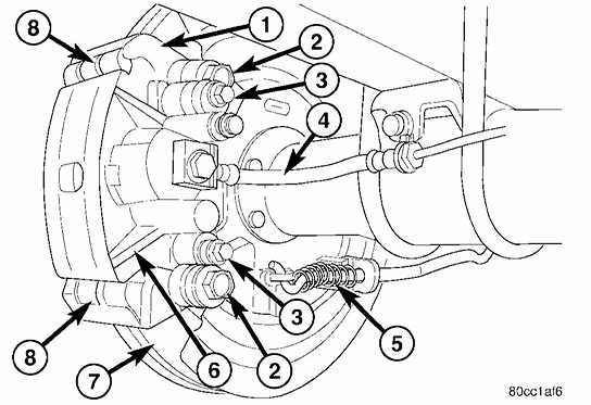
Alright, let's dive into the brake lines of your 2004 Dodge Ram 1500. Understanding the brake line diagram isn’t just about impressing your buddies; it's crucial for proper diagnosis, repair, and even modification of your braking system. Whether you're chasing down a leak, upgrading to stainless steel lines, or simply expanding your automotive knowledge, this breakdown will give you the confidence you need.
Purpose of the Brake Line Diagram
Why bother with a diagram? Simple. It's your roadmap to the entire braking system. It illustrates the layout of brake lines, components, and their interconnections. This helps with:
- Troubleshooting: Quickly identify potential problem areas when diagnosing leaks, soft brake pedals, or uneven braking.
- Repair: Ensures correct routing when replacing damaged lines, preventing kinks and ensuring proper fluid flow.
- Modification: Provides a clear understanding of the system for upgrades like stainless steel lines, brake boosters, or even complete brake swaps.
- Learning: Deepens your understanding of how the hydraulic braking system functions on your specific vehicle.
Key Specs and Main Parts (2004 Dodge Ram 1500)
Before we look at the diagram, let's define some key components. Keep in mind that configurations can vary slightly based on factors like ABS (Anti-lock Braking System) and the specific cab and bed configuration (Regular, Quad, Mega Cab; Short Bed, Long Bed). However, the fundamental principles remain the same.
- Master Cylinder: The heart of the braking system. It converts mechanical force from the brake pedal into hydraulic pressure. It typically has two separate reservoirs, one for the front brakes and one for the rear, providing redundancy in case of a leak in one system.
- Brake Booster: Uses engine vacuum to amplify the force applied to the master cylinder, reducing pedal effort.
- Proportioning Valve: Controls the pressure distribution between the front and rear brakes. This prevents rear wheel lockup during hard braking, which can lead to loss of control.
- Brake Lines: Steel tubing that carries brake fluid under pressure from the master cylinder to the wheel cylinders or calipers. They are typically a double-walled steel construction to withstand high pressure.
- Flexible Brake Hoses: Rubber or braided stainless steel hoses that connect the steel lines to the calipers or wheel cylinders. These hoses allow for suspension movement.
- Calipers (Front): Clamp onto the brake rotors, using brake pads to create friction and slow the vehicle. Usually a dual-piston design for increased stopping power.
- Wheel Cylinders (Rear): Located inside the rear brake drums, they push the brake shoes against the drum to create friction.
- Brake Rotors (Front): Cast iron discs that rotate with the wheels and provide a surface for the brake pads to grip.
- Brake Drums (Rear): Cast iron cylinders that rotate with the wheels and provide a surface for the brake shoes to grip.
- ABS Module (if equipped): Controls the anti-lock braking system, preventing wheel lockup during hard braking by modulating brake pressure to individual wheels. It includes a hydraulic control unit (HCU) and an electronic control unit (ECU).
- Brake Fluid Reservoir: Located on the master cylinder, this holds the brake fluid supply.
Common brake line sizes on the 2004 Ram 1500 are typically 3/16" (4.76mm) and 1/4" (6.35mm) OD (Outer Diameter). The fittings are usually standard inverted flare fittings.
Understanding Symbols on the Diagram
Brake line diagrams use standardized symbols. Here's what you’ll likely encounter:
- Solid Lines: Represent rigid steel brake lines.
- Dotted Lines: Often indicate vacuum lines (for the brake booster) or electrical wiring related to the ABS system.
- Different Colors: While not always present, different colors can indicate different circuits or sections of the braking system (e.g., front vs. rear).
- Circles/Squares: Typically represent connection points, junctions, or components like valves and sensors.
- Triangles: Often used to denote pressure test points.
It's essential to consult the specific legend accompanying your diagram for accurate interpretation. Do not assume the meaning of a symbol.
How the Brake System Works (Simplified)
Here’s a simplified explanation of how the hydraulic braking system functions:
- When you press the brake pedal, you push the master cylinder piston(s).
- This forces brake fluid through the brake lines and hoses.
- The fluid pressure acts on the calipers (front) and wheel cylinders (rear).
- The calipers clamp the brake pads against the rotors, and the wheel cylinders push the brake shoes against the drums.
- This friction slows the rotation of the wheels, stopping the vehicle.
The proportioning valve ensures that the rear brakes don't lock up prematurely, maintaining stability during braking. The ABS (if equipped) monitors wheel speed and modulates brake pressure to prevent wheel lockup, enhancing steering control during emergency stops.
Real-World Use & Basic Troubleshooting
Let's say you notice a brake fluid leak under your truck. The diagram can help pinpoint the source. Follow these steps:
- Identify the leak location: Determine which wheel area the leak is coming from, or if it's near the master cylinder or proportioning valve.
- Consult the diagram: Trace the brake line from the master cylinder to the affected wheel. Note any connections, junctions, or components along the way.
- Inspect the lines: Check for corrosion, cracks, or damage, especially near fittings and connections.
- Check the hoses: Look for cracks, bulges, or leaks in the flexible brake hoses.
- Inspect the components: Examine the calipers, wheel cylinders, and proportioning valve for leaks or damage.
A spongy brake pedal can indicate air in the brake lines. The diagram will help you identify the bleeder screws on each caliper and wheel cylinder, allowing you to properly bleed the brakes.
Common Issues:
- Corroded Brake Lines: A major issue, especially in regions with harsh winters and road salt.
- Leaky Brake Hoses: Rubber hoses deteriorate over time and can develop cracks and leaks.
- Sticking Calipers: Can cause uneven braking and premature brake pad wear.
Safety Considerations
Brakes are critical! Any work on your braking system should be approached with extreme caution.
- Brake Fluid: Brake fluid is corrosive and can damage paint. Wear gloves and eye protection when handling it.
- High Pressure: The braking system operates under high pressure. Never disconnect brake lines while the system is pressurized.
- Bleeding Brakes: Ensure proper bleeding to remove all air from the lines. Air in the system can significantly reduce braking performance.
- DOT Rating: Always use the correct type of brake fluid (DOT 3, DOT 4, etc.) specified in your vehicle's owner's manual. Mixing different types of brake fluid can damage the system.
- Torque Specs: Always tighten brake line fittings to the correct torque specifications. Overtightening can damage the fittings, while undertightening can lead to leaks.
Critical note: When working on ABS systems, it is highly recommended to consult a qualified mechanic. Improper handling of the ABS module can lead to system malfunctions.
Warning: Brake fluid is hygroscopic, meaning it absorbs moisture from the air. Over time, this moisture can corrode internal brake components and reduce braking performance. It's essential to flush and replace the brake fluid every 2-3 years, or as recommended in your vehicle's owner's manual.
By understanding the 2004 Dodge Ram 1500 brake line diagram and the components it represents, you'll be better equipped to diagnose, repair, and maintain your truck's braking system. Always prioritize safety and consult a professional if you're unsure about any procedure.