
2004 Ford Expedition Vacuum Hose Diagram
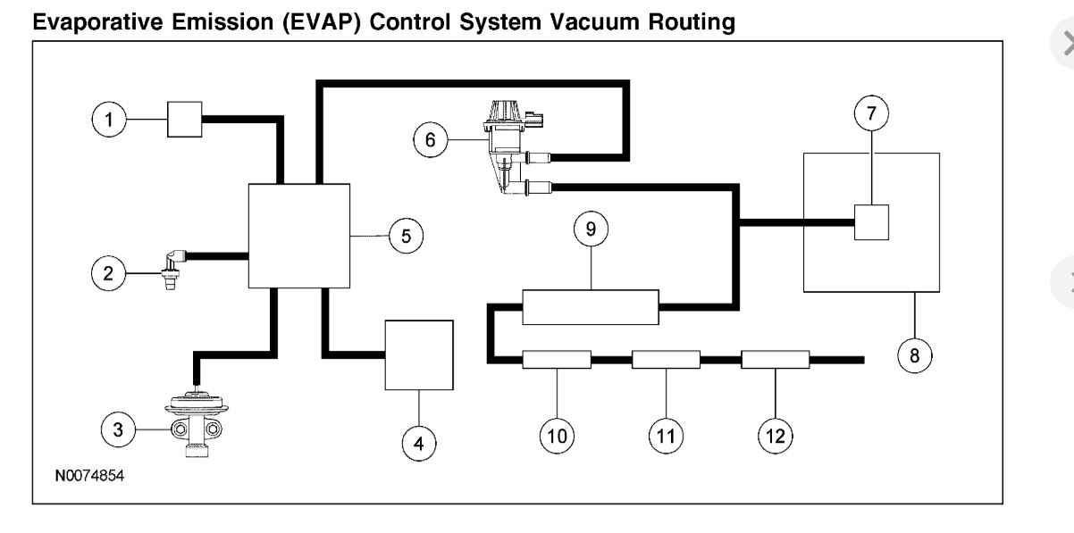
Let's dive into the often-overlooked but critically important world of vacuum hoses in your 2004 Ford Expedition. This article will be your guide to understanding the vacuum hose diagram for this vehicle, why it matters, how to read it, and how to use it for troubleshooting. Whether you're tackling a repair, performing routine maintenance, or simply want to deepen your understanding of your Expedition, this guide will provide the insights you need.
Purpose of the 2004 Ford Expedition Vacuum Hose Diagram
The vacuum hose diagram is essentially a roadmap of the vacuum system within your 2004 Ford Expedition. The vacuum system plays a vital role in controlling numerous engine and accessory functions. Understanding this diagram allows you to:
- Diagnose Vacuum Leaks: Vacuum leaks can cause a myriad of problems, from poor engine performance and rough idling to decreased fuel economy and malfunctioning accessories.
- Properly Route Hoses: During engine repairs or modifications, hoses can easily be disconnected and misrouted. The diagram ensures correct reconnection.
- Identify Components: The diagram helps you identify specific vacuum-operated components and their function within the system.
- Perform Maintenance: Routine inspection of vacuum hoses can prevent future issues. The diagram helps you locate and inspect all relevant hoses.
- General Learning: Even if you're not currently experiencing issues, understanding the vacuum system can enhance your overall knowledge of your vehicle's operation.
Key Specs and Main Parts of the Vacuum System
Before we dissect the diagram, let's familiarize ourselves with the key components of the 2004 Ford Expedition's vacuum system. Keep in mind that slight variations may exist depending on the engine configuration (4.6L or 5.4L V8).
- Vacuum Source: The primary source of vacuum is the engine intake manifold. As the pistons move, they create a negative pressure (vacuum) within the manifold.
- Vacuum Reservoir: This is a storage container (usually a black plastic sphere or cylinder) that stores vacuum. This provides a consistent vacuum source when engine vacuum fluctuates.
- Vacuum Hoses: These are the flexible rubber or plastic tubes that connect the vacuum source to various vacuum-operated components. They are available in various sizes, commonly between 1/8" and 1/2" inner diameter.
- Check Valves: These one-way valves allow vacuum to flow in one direction only, preventing backflow and maintaining vacuum in certain circuits.
- Vacuum Actuators: These devices convert vacuum pressure into mechanical motion. Examples include those used for the climate control dampers, cruise control, and 4WD system (if equipped).
- Vacuum Switches: These switches use vacuum to control electrical circuits.
- EGR Valve (Exhaust Gas Recirculation): While the EGR system is emissions-related, the EGR valve itself is often vacuum-operated, regulating the amount of exhaust gas recirculated back into the intake manifold.
- PCV Valve (Positive Crankcase Ventilation): The PCV system relies on vacuum to draw crankcase vapors into the intake manifold for combustion.
Understanding the Symbols and Markings on the Diagram
Vacuum diagrams use specific symbols and conventions to represent components and connections. Here's a breakdown of common markings:
- Solid Lines: These typically represent the main vacuum lines connecting components.
- Dotted or Dashed Lines: These can indicate control lines, smaller vacuum lines, or electrical connections related to the vacuum system.
- Arrows: Indicate the direction of vacuum flow.
- Component Symbols: The diagram will use simplified symbols to represent components like the vacuum reservoir, check valves, actuators, and switches. Consult the diagram's legend or your vehicle's service manual to correctly identify each symbol.
- Color Coding (If Present): Some diagrams use color coding to differentiate between various vacuum circuits. For instance, one color might represent the climate control system, while another represents the EGR system. However, many diagrams are black and white, relying on labels and line styles instead.
- Labels: Each vacuum line and component will be labeled with a code or abbreviation identifying its function or destination. For example, "VAC RES" might indicate a line connected to the vacuum reservoir, while "EGR SOL" might indicate the EGR solenoid.
How the Vacuum System Works on Your Expedition
The engine's intake manifold generates vacuum, which is then distributed throughout the system via vacuum hoses. This vacuum operates various accessories and emissions controls. For instance:
- Climate Control: Vacuum actuators control the blend doors and mode doors in the HVAC system, directing airflow to different vents. A vacuum leak in this system can result in air blowing only from the defrost vents.
- Cruise Control: In older systems, vacuum was used to control the throttle position, maintaining a set speed. While newer vehicles use electronic throttle control (ETC), vacuum might still be used for vacuum release mechanisms (VRM) for safety cutoff.
- EGR System: Vacuum controls the EGR valve, allowing a metered amount of exhaust gas to recirculate into the intake manifold, reducing combustion temperatures and NOx emissions.
- PCV System: Vacuum draws crankcase vapors through the PCV valve and into the intake manifold, preventing pressure buildup in the crankcase and reducing emissions.
- 4WD System (If Equipped): Vacuum can be used to engage and disengage the front axle in some 4WD systems.
Real-World Use: Basic Troubleshooting Tips
The vacuum diagram is invaluable for troubleshooting vacuum-related issues. Here are some basic tips:
- Visual Inspection: Start by visually inspecting all vacuum hoses for cracks, breaks, or disconnections. Pay close attention to areas where hoses connect to fittings. Old hoses can become brittle and crack over time.
- Listen for Hissing: A hissing sound coming from the engine compartment often indicates a vacuum leak. Use a length of hose as a stethoscope to pinpoint the source of the hiss.
- Use a Vacuum Gauge: A vacuum gauge can be connected to a vacuum port on the intake manifold to measure engine vacuum. Readings outside the normal range can indicate a problem with the vacuum system or the engine itself.
- Smoke Testing: A smoke machine can be used to introduce smoke into the vacuum system. The smoke will escape from any leaks, making them easy to identify.
- Component Testing: Use a hand-held vacuum pump to test vacuum-operated components like actuators and switches. Apply vacuum to the component and observe its operation.
For example, if your climate control is malfunctioning, start by inspecting the vacuum hoses and connections related to the HVAC system. Refer to the diagram to locate the vacuum reservoir, actuators, and control valves. A disconnected or cracked hose in this circuit is a likely culprit.
Safety Considerations
While working on the vacuum system is generally safe, be mindful of the following:
- Hot Engine: Avoid working on the vacuum system when the engine is hot. Allow the engine to cool down completely before beginning any repairs.
- Sharp Objects: Be careful when handling tools and hoses to avoid cuts and scrapes.
- Fuel Lines: Be aware of the location of fuel lines and avoid damaging them. Fuel leaks are a serious fire hazard.
- EGR Valve: The EGR valve can become very hot during engine operation. Allow it to cool down before handling it.
- Electrical Components: Be cautious when working around electrical components. Disconnect the negative battery cable before performing any electrical work.
- Avoid smoking or open flames: Never smoke or use open flames near the engine compartment, especially when working on the fuel system.
Note: The information provided here is a general guide and may not cover all specific details of your 2004 Ford Expedition. Always refer to your vehicle's service manual for the most accurate and up-to-date information.
By now, you should have a solid understanding of the 2004 Ford Expedition vacuum hose diagram and its importance. With this knowledge, you're well-equipped to diagnose and repair vacuum-related issues, keeping your Expedition running smoothly.
We have the complete, high-resolution vacuum hose diagram available for download. This file will be invaluable for your repair and maintenance tasks. You can access it by clicking the download link provided [hypothetical link to download file here]. Good luck with your project!