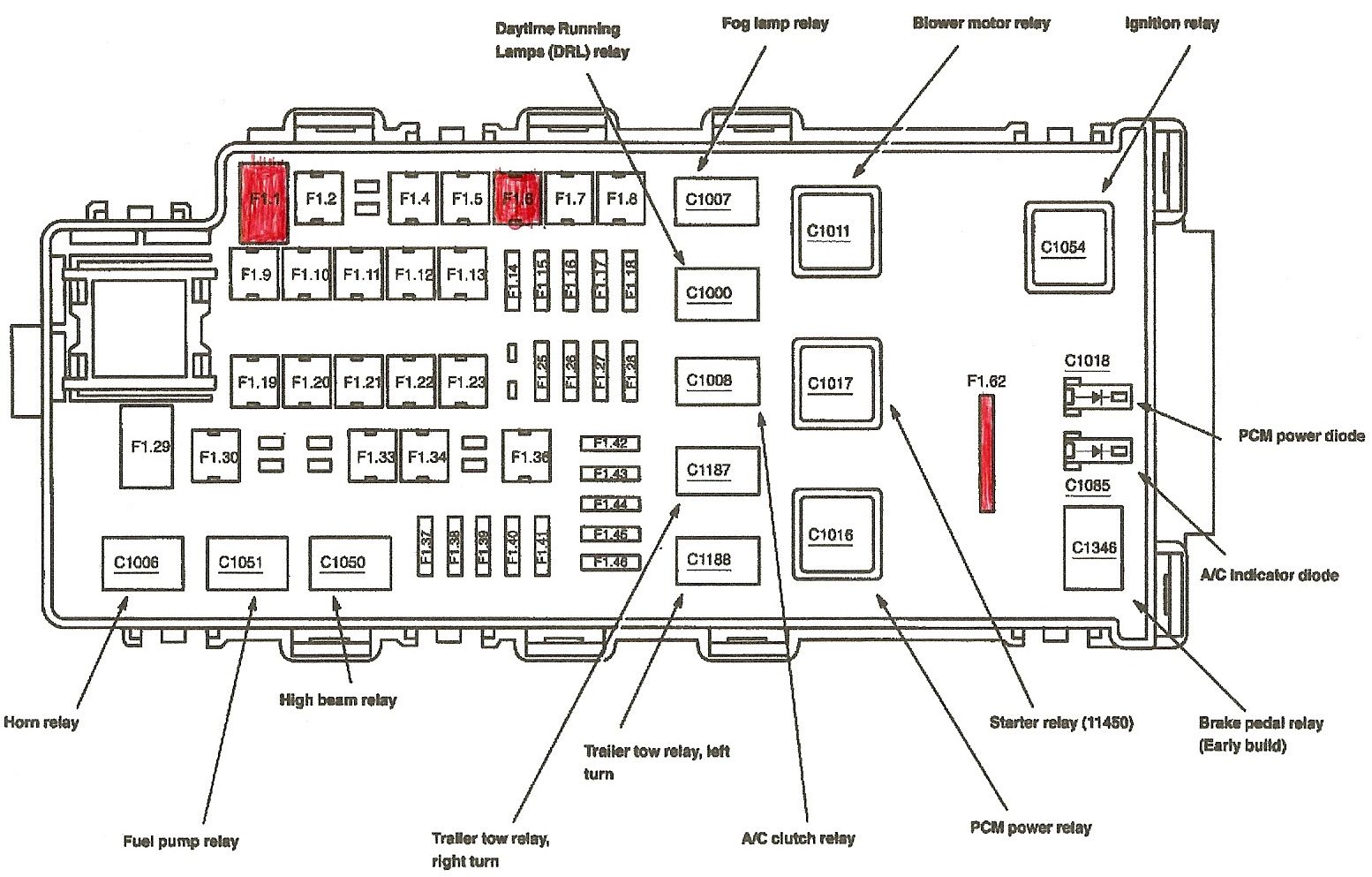
2004 Ford Explorer Fuse Box Diagram Under Hood
Understanding your vehicle's electrical system is crucial for both routine maintenance and complex repairs. A key component of this system is the fuse box, and knowing how to interpret its diagram is essential for any experienced DIYer. This article focuses specifically on the 2004 Ford Explorer under-hood fuse box diagram, providing a detailed breakdown of its purpose, components, symbols, and how to use it for troubleshooting.
Purpose of the Fuse Box Diagram
The fuse box diagram is essentially a roadmap of your vehicle's electrical circuits. It tells you which fuse protects which component, making it invaluable for several reasons:
- Troubleshooting Electrical Issues: When an electrical component fails (e.g., a headlight, the radio, the power windows), the first step is often to check the corresponding fuse. The diagram tells you exactly which fuse to inspect.
- Performing Electrical Modifications: If you're adding aftermarket accessories (e.g., auxiliary lights, a new stereo), you'll need to tap into the existing electrical system. The diagram helps you identify suitable circuits and ensures you're not overloading any existing fuses.
- Understanding the Electrical System: Even if you're not actively working on your car, studying the diagram can give you a better understanding of how the various electrical components are interconnected and how the entire system operates.
- Replacing a Blown Fuse: Identifying the correct replacement fuse is faster and easier using the diagram.
Key Specs and Main Parts of the 2004 Ford Explorer Under-Hood Fuse Box
The 2004 Ford Explorer's under-hood fuse box is typically located in the engine compartment, often near the battery. It's a rectangular plastic box with a hinged cover. The cover itself usually has the fuse diagram printed on the inside. Here are some key specs to keep in mind:
- Fuse Types: The 2004 Explorer primarily uses blade-type fuses, which are small, color-coded fuses with two prongs. Common types include ATO (Automotive Transportation Outlines) and mini-ATO fuses.
- Fuse Ratings: Fuses are rated in Amperes (A), which indicates the maximum current they can safely handle. Common ratings include 5A, 7.5A, 10A, 15A, 20A, 25A, 30A, and higher. It is critical to replace a blown fuse with one of the exact same amperage rating. Using a higher-rated fuse can damage the circuit.
- Relays: The fuse box also houses relays. A relay is an electrically operated switch that allows a low-current circuit to control a high-current circuit. Relays are used for components like the starter motor, headlights, and air conditioning compressor.
- Circuit Breakers: Some circuits may be protected by circuit breakers instead of fuses. Circuit breakers are reusable and automatically reset themselves after a short overload (though they may need manual resetting after a prolonged overload).
Main Components:
- Fuses: Overcurrent protection devices that melt and break the circuit when the current exceeds their rating.
- Relays: Electrically operated switches that control high-current circuits using a low-current signal.
- Circuit Breakers: Reusable overcurrent protection devices that interrupt the circuit and reset after an overload.
- Wiring Harness Connectors: These connect the fuse box to the vehicle's wiring harness.
- Fuse Puller: A small plastic tool usually located in the fuse box to safely remove fuses.
Understanding Fuse Box Diagram Symbols
Fuse box diagrams use a variety of symbols and conventions to represent the different circuits and components. Here's a breakdown of some common ones:
- Lines: Solid lines typically represent the wiring connecting the fuse to the component it protects. Dashed lines might indicate a ground connection or a connection to another part of the electrical system.
- Rectangles: Often represent fuses. The number inside or next to the rectangle indicates the fuse's amperage rating.
- Circles or Squares with Letters: These typically represent relays. The letter inside the shape identifies the relay's function (e.g., "F" for fuel pump relay, "H" for headlight relay).
- Color Coding: The diagram might use color coding to indicate the wire gauge or the circuit's function. However, this is less common on fuse box diagrams and more prevalent on complete wiring schematics.
- Icons: Some diagrams use icons to represent the components being protected. For example, a headlight icon might indicate the headlight circuit, or a radio icon might indicate the radio circuit. These icons can vary, so familiarity with your vehicle's specific diagram is key.
It's important to note that diagrams can vary slightly. The best resource is always the diagram specifically printed on the inside of your fuse box cover or in your owner's manual. They are also available online through reputable vehicle repair information services.
How It Works: The Electrical Flow
The fuse box acts as a central distribution point for electrical power in the vehicle. Power from the battery flows into the fuse box and is then distributed to various circuits through individual fuses. Each fuse protects a specific circuit from overcurrent. If a fault occurs in a circuit, causing excessive current flow (e.g., a short circuit), the fuse will blow, interrupting the current flow and preventing damage to the wiring and components. The diagram is crucial because it tells you exactly which fuse corresponds to which circuit. When tracing a problem, you follow the flow of electricity from the battery, through the fuse box, and to the device. Knowing the order of operations is key for efficient troubleshooting.
Real-World Use: Basic Troubleshooting Tips
Here's how to use the fuse box diagram for basic troubleshooting:
- Identify the Problem: Determine which component is not working.
- Locate the Diagram: Find the fuse box diagram (usually inside the fuse box cover or in your owner's manual).
- Find the Corresponding Fuse: Use the diagram to identify the fuse that protects the malfunctioning component.
- Inspect the Fuse: Remove the fuse and visually inspect it. A blown fuse will have a broken filament inside. Use a multimeter to confirm continuity if visual inspection is inconclusive.
- Replace the Fuse: If the fuse is blown, replace it with a new fuse of the exact same amperage rating.
- Test the Component: After replacing the fuse, test the component to see if it is now working.
- If the Fuse Blows Again: If the new fuse blows immediately or shortly after replacement, there is likely a short circuit or other fault in the circuit. Further diagnostics are needed. This may require professional assistance.
Safety Considerations
Working with electrical systems can be dangerous. Always take the following precautions:
- Disconnect the Battery: Before working on any electrical components, disconnect the negative terminal of the battery to prevent accidental short circuits.
- Use Insulated Tools: Use insulated tools to avoid electric shock.
- Never Bypass a Fuse: Never replace a fuse with a wire or other conductive material. This can cause a fire or serious damage to the electrical system.
- Be Careful Around High-Current Components: Components like the starter motor and alternator carry high currents and can be dangerous if mishandled.
- Don't Work in Wet Conditions: Avoid working on electrical systems in wet or damp environments.
- Avoid High Voltage Components: Some components, like the ignition system, generate high voltages. Avoid contact with these components while the engine is running.
Important Note: The starter solenoid/relay is one of the riskiest components. Disconnecting the battery is especially important to safely service the starter system. Even with the battery disconnected, residual current can be present, so handle with care.
By understanding the fuse box diagram and following these safety precautions, you can confidently troubleshoot and repair many electrical problems on your 2004 Ford Explorer. Remember, if you're unsure about any aspect of the repair, it's always best to consult a qualified mechanic.
We have a copy of the 2004 Ford Explorer Under-Hood Fuse Box Diagram available for download. This file contains a high-resolution image suitable for printing and easy reference during your repairs. Contact us for the file.