2004 Ford F150 Stereo Wiring Diagram
The 2004 Ford F150, part of the 11th generation of this iconic truck, represents a pivotal point in automotive electronics. Understanding its stereo wiring diagram is crucial for various tasks, from basic speaker replacement to complex aftermarket head unit installations. This article provides a comprehensive breakdown of the 2004 F150 stereo wiring diagram, empowering you to confidently tackle audio-related projects.
Purpose of Understanding the Wiring Diagram
Why bother with a wiring diagram? Several scenarios make it indispensable:
- Repairing Damaged Wiring: Rodents, age, and accidental damage can compromise the factory wiring harness. A diagram helps you identify and repair broken or shorted wires.
- Upgrading the Stereo System: Installing a new head unit, amplifier, or speakers often requires tapping into existing wiring. The diagram shows you which wires control which functions, preventing damage to your vehicle's electrical system.
- Diagnosing Audio Problems: Is your radio not turning on? Are speakers cutting in and out? The wiring diagram is your roadmap for tracing the signal path and pinpointing the source of the problem.
- Learning About Automotive Electrical Systems: Even if you're not actively working on your stereo, understanding the wiring diagram is a valuable learning experience that deepens your knowledge of automotive electrical systems in general.
Key Specs and Main Parts of the 2004 F150 Stereo System
Before diving into the diagram itself, let's understand the main components and their specifications:
- Head Unit: The central control unit, responsible for receiving radio signals, playing CDs (if equipped), and providing audio output. The factory head unit is typically a DIN (single-DIN or double-DIN, depending on the trim level) size. DIN refers to the Deutsches Institut für Normung (German Institute for Standardization) standards for radio sizes.
- Speakers: The 2004 F150 typically has speakers in the front doors and rear doors (or rear of the cab in a standard cab model). Speaker sizes can vary depending on the trim level, but 6x8 inch or 5x7 inch speakers are common. Aftermarket upgrades often involve replacing these with higher-quality speakers.
- Amplifier (Optional): Some higher trim levels may include a factory amplifier. The amplifier boosts the audio signal from the head unit to drive the speakers with more power. Location varies, but it's often behind the rear seat or under the center console.
- Wiring Harness: The bundle of wires that connects all the components. The factory harness uses specific connectors that may not be compatible with aftermarket head units, requiring the use of adapter harnesses.
- Antenna: Receives radio signals. The 2004 F150 typically has an antenna located on the fender or roof.
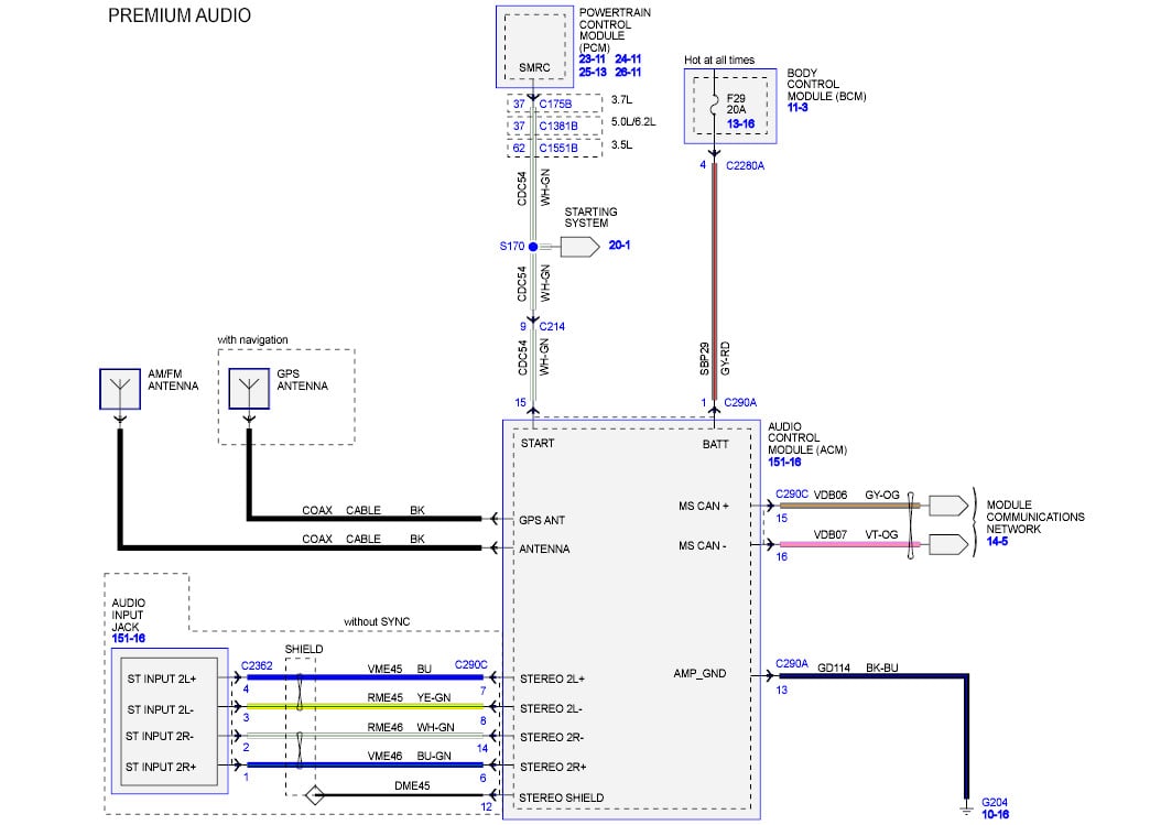
Understanding the Symbols and Conventions in the Diagram
A wiring diagram is a symbolic representation of an electrical circuit. Here's a breakdown of common symbols and conventions:
- Lines: Lines represent wires. The thickness of the line does not necessarily indicate wire gauge.
- Colors: Wires are often color-coded. The diagram will include a legend that specifies the color associated with each function (e.g., red for power, black for ground, etc.). Typical color codes include:
- Red: Usually positive (+) power.
- Black: Usually ground (-).
- Yellow: Usually constant 12V power (for memory).
- Blue: Usually remote turn-on for an amplifier.
- White/Gray: Often speaker wires.
- Connectors: Represented by various shapes, often squares or circles. The diagram will identify the connector by a numerical code or letter. These codes are critical for identifying the correct connector in the vehicle.
- Ground Symbol: A symbol resembling an inverted pyramid or a series of horizontal lines, indicating a connection to the vehicle's chassis ground.
- Fuses: Represented by a zigzag line inside a circle or rectangle. The diagram will indicate the fuse amperage rating.
- Component Symbols: Each component (e.g., head unit, speaker, amplifier) is represented by a specific symbol. These symbols are usually labeled with the component name.
How the Stereo System Works: A Simplified Explanation
The 2004 F150 stereo system functions as follows:
- Power Supply: The head unit receives power from the vehicle's battery through a fused circuit. There are typically two power wires: one for constant 12V (for memory) and one that is switched with the ignition.
- Signal Input: The head unit receives audio signals from various sources, such as the radio antenna, CD player, or auxiliary input.
- Signal Processing: The head unit processes the audio signal, allowing you to adjust the volume, tone, and balance.
- Amplification: The head unit amplifies the audio signal (or sends it to an external amplifier if equipped).
- Speaker Output: The amplified audio signal is sent to the speakers, which convert the electrical signal into sound waves.
The wiring diagram shows the connections between all of these components, allowing you to trace the signal path and understand how each component interacts with the others.
Real-World Use: Basic Troubleshooting Tips
Here are a few basic troubleshooting scenarios and how the wiring diagram can help:
- No Power to the Head Unit: Check the fuses related to the radio. The diagram will show you the location and amperage rating of these fuses. Use a multimeter to verify that power is reaching the head unit. If not, trace the power wire back to the fuse box, looking for breaks or shorts.
- One Speaker Not Working: Use the diagram to identify the speaker wires for the affected speaker. Check the wiring connections at the speaker and the head unit. Use a multimeter to test the speaker wire for continuity. If there's no continuity, there's a break in the wire.
- Static or Distortion: Check the speaker wires for shorts to ground. A short to ground can cause static or distortion in the audio signal. The diagram will help you identify the ground points in the system.
Safety Precautions When Working with Automotive Electrical Systems
Working with automotive electrical systems can be dangerous. Follow these safety precautions:
- Disconnect the Battery: Always disconnect the negative terminal of the battery before working on any electrical components. This prevents accidental shorts and electrical shocks.
- Use a Multimeter: A multimeter is an essential tool for diagnosing electrical problems. Learn how to use it to test for voltage, continuity, and resistance.
- Be Careful with Airbags: The 2004 F150 is equipped with airbags. Avoid disturbing the airbag wiring, as this could trigger accidental deployment. The wiring diagram will help you identify the airbag circuits.
- Insulate Connections: When making wiring connections, use proper connectors or solder and heat shrink tubing to ensure secure and insulated connections.
- Be Aware of High-Current Circuits: The starter circuit and alternator circuit carry high currents. Avoid working on these circuits unless you are experienced and have the proper tools and knowledge.
Access to the 2004 Ford F150 Stereo Wiring Diagram
Having the complete and accurate wiring diagram is essential for successful repairs and upgrades. We have the full, detailed 2004 Ford F150 stereo wiring diagram available for download. It's crucial to reference the correct diagram for your specific vehicle to avoid errors. Remember to verify that the diagram matches your truck's trim level and options before beginning any work. A wrong connection can damage your system or your truck's electrical system, which can be expensive to repair. Check the date codes on the harness if possible, and always double check your work before connecting the battery after changes.