2004 Ford Ranger Fuse Box Diagram Under Hood
If you're wrenching on a 2004 Ford Ranger, understanding its fuse box is crucial. This article breaks down the 2004 Ford Ranger under-hood fuse box diagram, explaining its purpose, components, symbols, and how to use it for troubleshooting. Think of this as your cheat sheet for electrical issues.
Purpose of the Fuse Box Diagram
The fuse box diagram serves as a roadmap to your vehicle's electrical system. It's not just a pretty picture; it's essential for several reasons:
- Troubleshooting Electrical Problems: When something electrical stops working (like a headlight, radio, or power window), the fuse box is the first place to check. The diagram identifies which fuse corresponds to which circuit.
- Preventing Further Damage: Replacing a blown fuse with the correct amperage rating prevents further damage to the circuit. Using a fuse with a higher amperage can overload the circuit and cause a fire.
- Modifying or Adding Electrical Components: If you're adding aftermarket accessories (like a new sound system or auxiliary lights), you'll need to tap into the existing electrical system. The diagram helps you identify suitable circuits and their amperage ratings.
- Understanding the Electrical System: Even if nothing is broken, studying the diagram can give you a better understanding of how your vehicle's electrical system works.
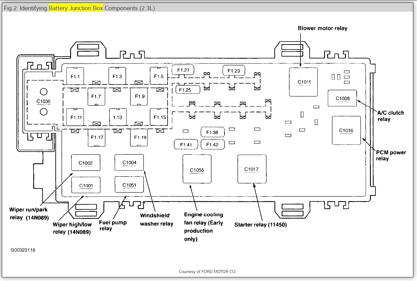
Key Specs and Main Parts of the 2004 Ford Ranger Under-Hood Fuse Box
The 2004 Ford Ranger's under-hood fuse box is typically located on the driver's side of the engine compartment, near the battery. It houses various fuses and relays that protect and control different electrical circuits. Here's a breakdown of the key components:
- Fuses: These are sacrificial devices designed to protect circuits from overcurrent. They contain a thin wire that melts and breaks the circuit when the current exceeds a certain level. Fuses are rated in amperes (amps), which indicates the maximum current they can handle. Common fuse types include blade fuses (ATO/ATC), mini-blade fuses, and cartridge fuses.
- Relays: These are electromechanical switches that control high-current circuits using a low-current signal. Relays are used to switch on and off components like the headlights, fuel pump, and starter motor. They consist of a coil, contacts, and a spring. When the coil is energized, it creates a magnetic field that pulls the contacts together, completing the circuit.
- Fuse Box Housing: This provides a protective enclosure for the fuses and relays, shielding them from dirt, moisture, and physical damage. It's usually made of durable plastic and has a cover that can be easily removed for access.
- Fuse Puller: A small plastic tool often included in the fuse box, used to safely remove fuses without damaging them or your fingers.
- Diagram Label: Usually located on the inside of the fuse box cover, this label provides a diagram of the fuse and relay locations, along with their corresponding functions and amperage ratings.
Understanding Fuse Box Symbols
The fuse box diagram uses symbols to represent different components and their functions. These symbols are often standardized, but it's always a good idea to consult the specific diagram for your 2004 Ford Ranger. Here are some common symbols you might encounter:
- Straight Line: Represents a wire or conductor.
- Zigzag Line: Represents a resistor or a load (e.g., a light bulb).
- Rectangle: Often represents a relay.
- Fuse Symbol (often a line broken by a curve): Represents a fuse. The amperage rating is usually indicated next to the symbol.
- Ground Symbol: Represents a connection to the vehicle's chassis ground.
- Color Codes: Wires are often color-coded to help identify their function. For example, red wires are often used for power, black wires for ground, and other colors for specific circuits. The diagram may include a color code chart.
- Icons: Many diagrams use icons to represent the components powered by each fuse. These icons can include a headlight, radio, windshield wiper, etc.
How the Fuse Box Works
The fuse box acts as a central distribution point for electrical power in your vehicle. Power from the battery flows through the main power distribution fuses and relays, then branches out to individual circuits. Each circuit is protected by a fuse that's sized appropriately for the components it powers.
When a fault occurs in a circuit (e.g., a short circuit), the current flow increases dramatically. This excessive current causes the fuse to blow, interrupting the circuit and preventing damage to the wiring and components. The relay acts as remote controlled switch. The vehicles computer can enable/disable different circuits.
Real-World Use: Basic Troubleshooting Tips
Here's how to use the fuse box diagram to troubleshoot common electrical problems:
- Identify the Problem: Determine which component isn't working. For example, "My headlights aren't working."
- Consult the Diagram: Locate the fuse that corresponds to the non-working component in the fuse box diagram. For example, "Headlights - Fuse #22."
- Inspect the Fuse: Use the fuse puller to remove the fuse. Visually inspect it. A blown fuse will have a broken filament (the thin wire inside).
- Test the Fuse: For a more accurate test, use a multimeter set to continuity. Place the probes on each end of the fuse. A good fuse will show continuity (a beep or a reading of 0 ohms).
- Replace the Fuse: If the fuse is blown, replace it with a new fuse of the exact same amperage rating. Never use a fuse with a higher amperage.
- Test the Component: After replacing the fuse, test the component to see if it's working again.
- If the Fuse Blows Again: If the new fuse blows immediately, there's a short circuit in the wiring or the component itself. You'll need to investigate further to find the source of the short. This may involve tracing wires, inspecting connectors, and testing components.
Safety Considerations
Working with electrical systems can be dangerous. Here are some safety precautions to keep in mind:
- Disconnect the Battery: Before working on any electrical circuits, disconnect the negative (-) terminal of the battery to prevent accidental short circuits.
- Use Insulated Tools: Always use insulated tools to avoid electric shock.
- Never Bypass Fuses: Never bypass a fuse with a wire or other conductive material. This can overload the circuit and cause a fire.
- Identify High-Current Circuits: Be especially careful when working with high-current circuits, such as the starter motor and alternator. These circuits can deliver a large amount of power and pose a significant shock hazard. Relays controlling fuel pumps and engine control units are sensitive; use care.
- Consult a Professional: If you're not comfortable working on electrical systems, consult a qualified mechanic.
This guide provides a comprehensive overview of the 2004 Ford Ranger under-hood fuse box diagram. Remember to always consult the specific diagram for your vehicle, as there may be slight variations depending on the model and trim level.
To further assist you, we have the original 2004 Ford Ranger fuse box diagram file available for download. This will provide you with a high-resolution, printable version for easy reference while you're working on your vehicle.