
2004 Honda Crv Cooling System Diagram
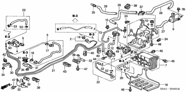
Let's dive into the cooling system of the 2004 Honda CRV. Understanding this system is crucial for maintaining your vehicle's longevity and preventing costly engine damage. This article will provide a detailed breakdown of the cooling system diagram, empowering you with the knowledge to diagnose issues, perform preventative maintenance, and even tackle some repairs yourself. We're talking about a system that's responsible for keeping your engine from literally melting down, so paying attention is key!
Purpose of the Cooling System Diagram
A cooling system diagram is essentially a roadmap of your CRV's cooling system. It illustrates the interconnected components, their relative positions, and the flow of coolant throughout the system. This diagram isn't just a pretty picture; it's a valuable tool for:
- Diagnosis: Identifying the source of leaks, overheating, or other cooling-related problems.
- Repair: Guiding the replacement of faulty components, ensuring correct routing of hoses, and proper reassembly.
- Maintenance: Understanding the system's layout allows for effective flushing, bleeding, and inspection of critical parts.
- Education: Learning the principles of engine cooling and how the various components contribute to efficient heat dissipation.
Having a clear understanding is essential, especially for those who enjoy tackling DIY projects or modifying their vehicles. It saves time, minimizes errors, and ultimately, saves money.
Key Specs and Main Parts (2004 Honda CRV Cooling System)
The 2004 Honda CRV cooling system is a liquid-cooled system, meaning it uses a coolant mixture (typically a 50/50 mix of antifreeze and distilled water) to absorb and dissipate heat. Key components include:
- Radiator: The primary heat exchanger. It consists of a core with fins that dissipate heat to the atmosphere. Hot coolant enters from the engine, is cooled as it flows through the radiator, and exits to return to the engine.
- Radiator Cap: A pressure-regulating valve. It maintains a specific pressure within the system (usually around 16 PSI), raising the boiling point of the coolant and improving cooling efficiency. It also incorporates a pressure-relief mechanism to prevent over-pressurization.
- Thermostat: A temperature-sensitive valve. It controls the flow of coolant to the radiator, allowing the engine to reach its optimal operating temperature quickly. Once the engine reaches a certain temperature, the thermostat opens, allowing coolant to flow to the radiator for cooling.
- Water Pump: A mechanical pump driven by the engine's accessory belt. It circulates coolant throughout the engine block, cylinder head, and radiator. A failing water pump can lead to overheating.
- Coolant Hoses: Flexible rubber hoses that connect the various components of the cooling system. These are prone to cracking and leaks over time due to heat and pressure.
- Coolant Reservoir (Overflow Tank): A plastic tank that allows for coolant expansion and contraction as the engine heats up and cools down. It helps maintain a consistent coolant level in the system.
- Cooling Fan(s): Electrically driven fans that draw air through the radiator when the vehicle is stationary or moving at low speeds. These are typically controlled by a temperature sensor.
- Engine Coolant Temperature (ECT) Sensor: This sensor provides data to the Engine Control Unit (ECU) about the engine's coolant temperature. The ECU uses this information to adjust fuel injection, ignition timing, and cooling fan operation.
Symbols and Diagram Conventions
Understanding the symbols used in the cooling system diagram is essential for accurate interpretation. Here's a breakdown of common symbols:
- Lines:
- Solid Lines: Typically represent coolant hoses or pipes.
- Dotted Lines: May indicate vacuum lines, electrical wiring, or less critical connections.
- Arrows: Indicate the direction of coolant flow.
- Component Symbols: Each component (radiator, water pump, thermostat, etc.) is represented by a simplified symbol. These symbols are generally standardized but may vary slightly between diagrams.
- Color Coding (if present): Some diagrams use color to differentiate between hot and cold coolant lines, or to distinguish between different types of fluids (e.g., coolant vs. oil). Typically, red indicates hot coolant, and blue indicates cooled coolant.
The diagram will also likely include notations for the sizes and types of hoses, as well as the location of various sensors and connections. Pay close attention to these details when working on the system.
How It Works: A Step-by-Step Explanation
The cooling system operates in a closed loop, constantly circulating coolant to remove heat from the engine and dissipate it into the atmosphere.
- Heat Absorption: As the engine runs, it generates a significant amount of heat. Coolant circulating through the engine block and cylinder head absorbs this heat.
- Circulation: The water pump forces the heated coolant out of the engine and towards the radiator.
- Thermostat Control: If the engine is cold, the thermostat remains closed, preventing coolant from flowing to the radiator. This allows the engine to reach its optimal operating temperature quickly. Once the engine reaches the setpoint, the thermostat opens.
- Heat Dissipation: The hot coolant flows into the radiator, where it passes through a network of tubes and fins. Air flowing through the radiator (either from the vehicle's movement or from the cooling fans) removes heat from the coolant.
- Coolant Return: The cooled coolant exits the radiator and returns to the engine to absorb more heat, completing the cycle.
- Overflow Tank: As the coolant heats up, it expands. Excess coolant flows into the coolant reservoir (overflow tank). When the engine cools down, the coolant contracts, and coolant is drawn back from the reservoir into the radiator, maintaining a consistent coolant level.
The ECT sensor monitors the coolant temperature and provides feedback to the ECU, which controls the cooling fans and adjusts other engine parameters to optimize cooling efficiency.
Real-World Use: Basic Troubleshooting Tips
Here are some common cooling system problems and how to troubleshoot them using the diagram:
- Overheating: Check the coolant level, inspect the radiator for leaks or blockages, verify the operation of the thermostat and water pump, and ensure the cooling fans are functioning correctly. The diagram will help you locate these components and trace the coolant flow.
- Coolant Leaks: Inspect all hoses, connections, the water pump, and radiator for signs of leaks. The diagram will show you the exact routing of the hoses and the location of all connections. Look for drips, stains, or a sweet smell (coolant).
- Low Coolant Level: Check for leaks (as above). If no leaks are found, the engine may be consuming coolant internally (e.g., due to a head gasket leak).
- Cooling Fan Malfunction: Check the fan motor, relay, and temperature sensor. The diagram will help you locate these components and trace the electrical wiring.
Remember to always allow the engine to cool down completely before working on the cooling system. Hot coolant can cause severe burns.
Safety Precautions
Working on the cooling system can be dangerous if proper precautions are not taken. Always wear eye protection and gloves. Hot coolant can cause severe burns, and pressurized coolant can spray out with considerable force.
- Never open the radiator cap when the engine is hot. Allow the engine to cool down completely before attempting to remove the cap.
- Be careful when working near the cooling fans. They can turn on automatically, even when the engine is off. Disconnect the battery to prevent accidental fan activation.
- Dispose of used coolant properly. Coolant is toxic and can harm the environment. Recycle it at a designated collection center.
- Be aware of the potential for steam burns when working with a hot engine. Steam can escape from the cooling system, causing severe burns.
The radiator and hoses are the primary areas of concern for heat-related injuries. The cooling fan(s) can cause injury if activated unexpectedly. Always take extra caution when working around these components.
With a copy of the 2004 Honda CRV cooling system diagram, you'll be well-equipped to understand, maintain, and repair this critical system. If you're a visual learner, this resource will be invaluable. Please use the contact at the end to request the diagram.