2004 Infiniti G35 Fuse Box Diagram
Let's dive into the fuse box diagram for a 2004 Infiniti G35. This is a crucial piece of information for anyone tackling electrical repairs, modifications, or even just trying to understand how your car's electrical system works. Understanding this diagram can save you time, money, and prevent potential electrical damage.
Purpose of the Fuse Box Diagram
The fuse box diagram is essentially a roadmap of your car's electrical circuits. It shows you the location of each fuse and relay, and what each component protects. Without it, you're basically guessing, which can lead to serious problems like blowing the wrong fuse, damaging components, or even starting a fire. A detailed diagram is invaluable for:
- Troubleshooting Electrical Issues: Identifying and replacing a blown fuse is the first step in diagnosing many electrical problems, from a non-working radio to a faulty power window.
- Performing Electrical Modifications: When adding aftermarket accessories like lights, amplifiers, or security systems, you need to tap into the existing electrical system safely. The diagram shows you which circuits are available and their amperage rating.
- General Understanding: Even if you're not actively working on your car, the diagram provides a better understanding of the electrical system's architecture and how different components are interconnected.
- Preventing Damage: Using the correct amperage fuse for a circuit is absolutely critical. The wrong fuse can lead to overheating, melted wires, and potentially a fire.
Key Specs and Main Parts of the 2004 G35 Fuse Box Diagram
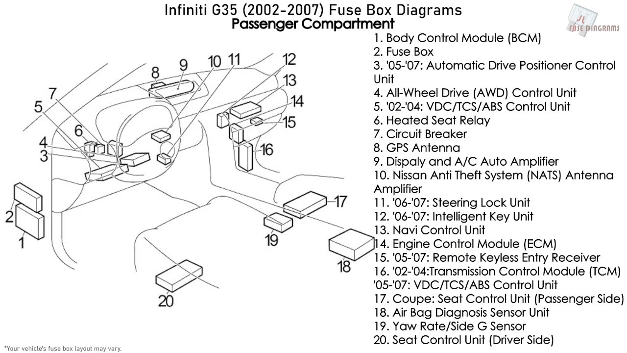
The 2004 Infiniti G35 typically has at least two fuse box locations: one inside the cabin (usually under the dashboard, near the steering wheel) and one in the engine compartment. Some models might even have a third, smaller fuse box near the battery. Each box protects different circuits and components. Here's a breakdown:
Main Fuse Box Locations:
- Interior Fuse Box: This generally controls interior components like the radio, lights, power windows, power locks, climate control, and instrument panel.
- Engine Compartment Fuse Box: This box manages engine-related circuits, including the fuel pump, ignition system, engine control unit (ECU), anti-lock braking system (ABS), and headlights.
Key Specs:
- Voltage: The G35 operates on a 12-volt DC electrical system. This is the standard for most modern vehicles.
- Amperage Ratings: Fuses are rated in amperes (amps), indicating the maximum current they can handle before blowing. Common fuse ratings include 5A, 7.5A, 10A, 15A, 20A, 25A, 30A, and higher. It is CRITICAL to replace a blown fuse with one of the same amperage rating.
- Fuse Types: The G35 typically uses blade-type fuses. These come in various sizes, including mini, standard, and maxi blade fuses. The diagram specifies the correct fuse type for each location.
Main Parts Shown on the Diagram:
- Fuse Locations: Clearly shows the physical location of each fuse within the fuse box. Usually labeled with a number or letter-number combination.
- Fuse Amperage Rating: Indicates the amp rating for each fuse, e.g., "10A," "20A."
- Circuit Description: Describes what the fuse protects. For example, "Radio," "Headlights (Left)," "Fuel Pump Relay."
- Relay Locations: The diagram also shows the location of relays, which are electromechanical switches that control higher-current circuits. Relays are often used for components like headlights, fuel pumps, and starters.
Understanding the Symbols on the Fuse Box Diagram
Fuse box diagrams use a standardized set of symbols to represent different components and connections. Understanding these symbols is key to interpreting the diagram correctly.
- Lines: Lines represent wires and electrical connections. Thicker lines may indicate higher-current circuits.
- Colors: Wire colors are often indicated on the diagram using abbreviations (e.g., BLU for blue, RED for red, BLK for black, GRN for green). These colors can help you trace wires within the vehicle.
- Fuse Symbol: Fuses are usually represented by a zigzag line enclosed in a rectangle or a simple rectangle with the amperage rating inside.
- Relay Symbol: Relays are typically represented by a coil symbol and a switch symbol. The coil represents the electromagnet that activates the switch.
- Ground Symbol: A ground symbol indicates a connection to the vehicle's chassis, which serves as the return path for the electrical current.
- Component Symbols: Other symbols may represent specific components like lamps, motors, or sensors. These symbols are usually labeled with a descriptive name.
How the Fuse Box Works
The fuse box is designed to protect the electrical circuits from overcurrent conditions, which can be caused by short circuits or excessive loads. When the current in a circuit exceeds the fuse's amperage rating, the fuse's internal element melts, breaking the circuit and preventing further damage. This is a critical safety feature.
Relays, on the other hand, are used to control high-current circuits with low-current signals. For example, the headlight switch in your car might only carry a small amount of current, but it controls a relay that switches on the high-current circuit powering the headlights. This prevents the headlight switch from being overloaded and damaged.
Real-World Use: Basic Troubleshooting Tips
Here's how to use the fuse box diagram to troubleshoot a common electrical problem:
- Identify the Problem: Determine which component is not working (e.g., the radio).
- Consult the Diagram: Locate the fuse that protects the circuit for the non-working component using the fuse box diagram.
- Inspect the Fuse: Remove the fuse and visually inspect it. Look for a broken filament inside the fuse. If the filament is broken, the fuse is blown.
- Replace the Fuse: Replace the blown fuse with a new fuse of the same amperage rating. Do not use a fuse with a higher amperage rating, as this could damage the circuit.
- Test the Component: Turn on the component to see if it now works. If the fuse blows again immediately, there is likely a short circuit in the wiring or the component itself. This requires further investigation.
Safety Considerations
Working with electrical systems can be dangerous if you're not careful. Here are some important safety precautions:
- Disconnect the Battery: Before working on the electrical system, disconnect the negative terminal of the battery. This prevents accidental shorts and electrical shocks.
- Use the Correct Fuse: Always replace a blown fuse with one of the same amperage rating. Using a higher-rated fuse can overload the circuit and cause a fire.
- Avoid Working in Wet Conditions: Never work on the electrical system in wet or damp conditions. Water is a conductor of electricity and can increase the risk of electric shock.
- Be Aware of High-Current Circuits: Some circuits, such as the starter motor circuit and the alternator circuit, carry very high currents. Be extremely careful when working with these circuits.
- Airbag System: The airbag system is also controlled by fuses. Improperly handled, it can cause injury. Consult the vehicle repair manual for the safest way to disconnect the battery to avoid accidental airbag deployment.
By understanding the fuse box diagram and following these safety precautions, you can safely and effectively troubleshoot and repair electrical problems in your 2004 Infiniti G35. Remember, if you're not comfortable working on the electrical system, it's best to consult a qualified mechanic.
We have a copy of the 2004 Infiniti G35 fuse box diagram available for download. It provides detailed information on fuse locations, amperage ratings, and circuit descriptions. This document can be a valuable resource for your troubleshooting and repair efforts.