2004 Jeep Grand Cherokee Door Wiring Harness
Alright, let's dive into the 2004 Jeep Grand Cherokee door wiring harness. Understanding this system is crucial whether you're tackling a repair, planning a modification like adding aftermarket speakers, or just want a deeper understanding of your vehicle's electrical system. A reliable wiring diagram is your best friend when things go sideways, so let’s break it down.
Purpose: Why This Diagram Matters
Why bother with a wiring diagram in the first place? The answer is simple: effective troubleshooting and repair. Without a clear understanding of the door wiring harness, you're essentially working in the dark. A diagram gives you the blueprint to:
- Diagnose Electrical Issues: Trace shorts, opens, and high resistance problems.
- Perform Repairs: Properly splice wires, replace connectors, and avoid damaging other components.
- Install Accessories: Safely add new features like aftermarket speakers, power locks, or alarms.
- Understand the System: Gain a fundamental understanding of how the door's electrical components interact.
Think of it like this: the wiring diagram is the Rosetta Stone for your Jeep's electrical language. It translates complex circuits into easily understandable visuals.
Key Specs and Main Parts
The 2004 Jeep Grand Cherokee's door wiring harness isn't just a single cable; it's a complex network designed to manage various functions. Here's a breakdown of the key components you'll find:
- Main Harness: The primary bundle of wires that runs from the body of the Jeep into the door. This is where all the power and signal wires are routed.
- Connectors: These are the plugs that connect the harness to the various components within the door, such as the power window motor, door lock actuator, and speakers. These connectors are often keyed (designed to fit only one way) to prevent misconnections.
- Power Window Motor: Controls the raising and lowering of the window. It receives power and ground through the harness, along with control signals from the window switch.
- Door Lock Actuator: This small motor locks and unlocks the door. It also receives power and control signals through the harness.
- Speakers: The audio output devices. Speaker wires run from the radio (or amplifier) through the harness to the speaker terminals.
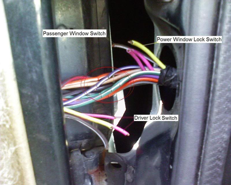
- Door Switch(es): These switches typically control interior lights and can also be integrated with the vehicle's security system. They signal when the door is open or closed.
- Power Mirror Controls: If equipped, these wires will control the mirror adjustment motors.
The specific gauge (thickness) of the wires will vary depending on the current requirements of the component they power. Larger gauge wires (e.g., 12 AWG) are used for high-current applications like the power window motor, while smaller gauge wires (e.g., 18 AWG or 20 AWG) are used for lower-current applications like speaker signals or door switch signals.
Symbols: Decoding the Wiring Diagram
A wiring diagram uses a specific set of symbols to represent different components and connections. Understanding these symbols is essential for interpreting the diagram correctly. Here's a brief overview:
- Lines: Lines represent wires. Solid lines usually indicate a direct connection, while dashed lines might represent a shielded cable or a less critical connection.
- Wire Colors: Each wire is identified by a color code (e.g., BLU for blue, GRN for green, RED for red). These color codes are crucial for identifying the correct wire when troubleshooting. The diagram will have a key explaining the abbreviations.
- Connectors: Connectors are typically represented by rectangles or circles with lines extending from them. Each connector is usually labeled with a unique identifier (e.g., C201, C302).
- Ground Symbols: Ground connections are represented by various symbols, often resembling an inverted triangle or a series of horizontal lines. These symbols indicate where the circuit connects to the vehicle's chassis (ground).
- Component Symbols: Each component (motor, switch, speaker) is represented by a specific symbol. These symbols are standardized, but it's always a good idea to refer to the diagram's legend for clarification.
Understanding the abbreviations is also vital. Look for a legend or key accompanying the diagram. Examples: "BLK" for black, "WHT" for white, "PPL" for purple.
How It Works
The door wiring harness acts as a central nervous system for the door's electrical functions. Power (typically +12V DC) and ground are supplied to the door through the main harness. From there, the power is distributed to the various components based on the signals received from switches, controllers, and other parts of the vehicle.
For example, when you press the power window switch, it sends a signal through the harness to the power window motor. This signal activates the motor, which then raises or lowers the window. Similarly, when you press the door lock button, a signal is sent to the door lock actuator, causing it to lock or unlock the door.
Signals are also sent out of the door through the harness. The door switch, for instance, signals the vehicle's computer when the door is opened or closed, which can trigger the interior lights or activate the alarm system.
Real-World Use: Basic Troubleshooting Tips
Here are a few common troubleshooting scenarios and how the wiring diagram can help:
- Power Window Not Working: Use the diagram to trace the power and ground wires to the window motor. Check for voltage at the motor connector when the switch is activated. If there's no voltage, trace the wiring back to the switch and check for continuity. A multimeter is your best friend here.
- Door Lock Not Working: Similar to the power window issue, trace the power and ground wires to the door lock actuator. Check for voltage when the lock/unlock button is pressed. If there's no voltage, check the switch and wiring connections.
- Speaker Not Working: Use the diagram to identify the speaker wires. Check for continuity between the radio (or amplifier) and the speaker terminals. If there's no continuity, there's likely a break in the wire.
Important: Always disconnect the battery's negative terminal before working on any electrical components to prevent shorts and potential damage.
Safety: Highlighting Risky Components
Working with electrical systems can be dangerous if proper precautions are not taken. Here are some key safety considerations:
- Airbag Systems: Be extremely careful when working near airbag components. Disconnecting and reconnecting these systems improperly can trigger airbag deployment, causing serious injury. Always disconnect the battery and wait at least 10 minutes before working on airbag-related wiring. Consult the service manual for specific instructions.
- Short Circuits: Short circuits can cause fires and damage to electrical components. Avoid creating shorts by carefully routing wires and ensuring that connections are secure.
- Battery Disconnect: Always disconnect the negative battery terminal before working on any electrical component. This eliminates the risk of accidental shorts and electrocution.
- Using a Multimeter: Learn how to use a multimeter safely and effectively. This tool is essential for diagnosing electrical problems.
Never probe into wire insulation without proper tools. Use back-probing techniques or insulation piercing probes to avoid damaging the wires. Damaged wires are a common cause of future problems.
Having access to the 2004 Jeep Grand Cherokee door wiring diagram is invaluable for any DIY mechanic. It empowers you to confidently diagnose and repair electrical issues, ensuring your Jeep stays on the road for years to come.
We have the complete wiring diagram available for download. Use it responsibly and safely!