2004 Jeep Grand Cherokee Door Wiring Harness Diagram
The 2004 Jeep Grand Cherokee is a solid SUV, but like any vehicle of that era, electrical gremlins can crop up. One of the most frequent problem areas involves the door wiring harness. Understanding the door wiring harness diagram is crucial for diagnosing and repairing issues related to power windows, door locks, speakers, and other door-related electrical components. This guide will equip you with the knowledge to interpret the diagram and tackle common problems, empowering you to save time and money on potentially expensive repairs.
Purpose of the Door Wiring Harness Diagram
The door wiring harness diagram is essentially a roadmap of the electrical system within your Jeep Grand Cherokee's door. It serves several critical purposes:
- Diagnosis: Pinpointing the source of electrical problems, such as a malfunctioning power window, door lock actuator, or speaker.
- Repair: Providing a visual reference for repairing damaged wiring, replacing faulty components, or performing modifications.
- Modification: Guiding the installation of aftermarket accessories, such as upgraded speakers, remote start systems, or custom lighting.
- Learning: Offering a deeper understanding of the vehicle's electrical system and how its components interact.
Without this diagram, you'd be flying blind, potentially causing more damage than good. It helps you trace circuits, identify connectors, and verify proper wire connections.
Key Specs and Main Parts
Before diving into the diagram itself, let's cover some key specifications and the main components involved in a typical 2004 Jeep Grand Cherokee door wiring harness:
- Voltage: Typically operates on a 12-volt DC system, powered by the vehicle's battery.
- Wire Gauge: Wire thickness varies depending on the current load it carries. Common gauges include 18, 16, 14, and 12 AWG (American Wire Gauge). Thicker wires are used for higher current applications like power windows.
- Connectors: Various multi-pin connectors are used to connect the harness to the vehicle's body and to individual components within the door. These are often color-coded or keyed to prevent misconnection.
- Ground Points: Critical for completing circuits. Usually attached to the door frame or body. A poor ground connection can cause a wide range of electrical problems.
- Components: The harness typically connects to the following:
- Power Window Motor: Controls the up and down movement of the window.
- Door Lock Actuator: Electrically controls the locking and unlocking of the door.
- Speaker: For audio output.
- Door Switch: Detects whether the door is open or closed, often triggering interior lights.
- Mirror Controls (if equipped): Controls the adjustment of the side mirrors.
- Courtesy Light: Illuminates when the door is opened.
Symbols, Lines, Colors, and Icons
Understanding the symbols, lines, colors, and icons used in the wiring diagram is paramount. Here's a breakdown of the most common ones:
- Lines: Represent wires. The thickness of the line sometimes, but not always, indicates the wire gauge.
- Colors: Wires are typically color-coded to aid in identification. Common colors include:
- Red (RD): Typically indicates a power supply wire.
- Black (BK): Typically indicates a ground wire.
- White (WT): Often used for signal wires or illumination circuits.
- Blue (BL): Varies depending on function.
- Green (GN): Varies depending on function.
- Yellow (YL): Varies depending on function.
The diagram should include a color key, so always refer to it.
- Symbols:
- Resistor: A zig-zag line.
- Capacitor: Two parallel lines.
- Diode: A triangle pointing to a line.
- Ground: Usually represented by a series of downward-pointing lines or a triangle.
- Switch: A break in a line that can be closed or opened to complete or interrupt a circuit.
- Connector: Often shown as a circle with lines entering and exiting.
- Fuse: A wavy line inside a rectangle, indicating a protective device that breaks the circuit if the current exceeds a safe level.
- Icons: Represent specific components, such as:
- Motor: Often depicted as a circle with an "M" inside.
- Speaker: Looks like a stylized speaker.
- Actuator: Varies, but often looks like a small box with arrows indicating movement.
- Numerical Designations: Each wire and connector pin may be assigned a numerical designation for easy referencing.
Pay close attention to the connector symbols and their associated pin numbers. These are crucial for identifying the correct wires to test or connect to.
How It Works: Circuit Flow
Understanding how the circuits flow within the door wiring harness is essential for effective troubleshooting. Here's a simplified overview:
- Power Source: Power originates from the vehicle's battery, often passing through a fuse or circuit breaker for protection.
- Switch Activation: When you operate a switch (e.g., power window switch), you complete a circuit.
- Current Flow: Current flows through the wiring harness to the intended component (e.g., power window motor).
- Component Activation: The component performs its function (e.g., the power window motor turns, raising or lowering the window).
- Ground Return: The current then returns to the vehicle's battery through a ground wire, completing the circuit.
A break or short circuit anywhere in this flow will cause the component to malfunction.
Real-World Use: Basic Troubleshooting Tips
Here are some practical troubleshooting tips using the wiring diagram:
- Start with the Basics: Check fuses related to the malfunctioning component. The diagram will show which fuse protects each circuit.
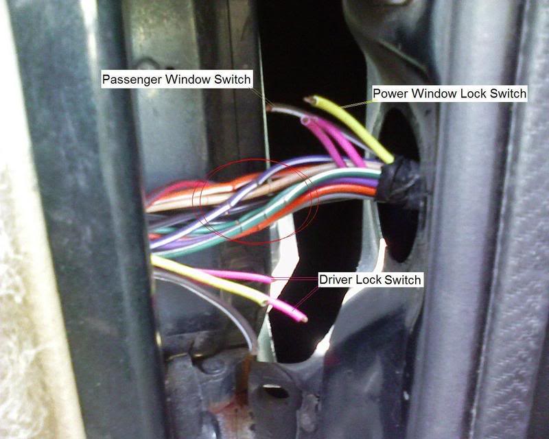
- Visual Inspection: Inspect the wiring harness for any signs of damage, such as frayed wires, corroded connectors, or rodent damage. Pay close attention to the area where the harness passes from the door to the body, as this area is prone to flexing and wire breakage.
- Voltage Testing: Use a multimeter to test for voltage at the component's connector. The diagram will show which pins should have voltage when the circuit is activated. If there's no voltage, trace the circuit back towards the power source.
- Continuity Testing: Use a multimeter to test for continuity (a complete circuit) in the ground wires and between components. A lack of continuity indicates a broken wire or a poor connection.
- Component Testing: If power and ground are present but the component still doesn't work, the component itself may be faulty. Consult the service manual for component-specific testing procedures.
For example, if your power window isn't working, start by checking the fuse. Then, use the wiring diagram to locate the power window motor connector. Use a multimeter to check for 12V at the appropriate pins when the window switch is activated. If there's no voltage, trace the wiring back towards the switch and the fuse box, checking for breaks or shorts along the way.
Safety: Highlighting Risky Components
Working with electrical systems can be dangerous. Always take the following precautions:
- Disconnect the Battery: Before working on any electrical component, disconnect the negative terminal of the battery to prevent accidental short circuits.
- Use Proper Tools: Use insulated tools to prevent shocks.
- Avoid Water: Never work on electrical systems in wet conditions.
- Identify SRS Components: Be extremely cautious when working near airbag (SRS) components. Accidental activation can cause serious injury. The wiring diagram will identify these components, often labeled with SRS or airbag symbols.
Always disconnect the battery before probing any electrical connections. This is especially important when working near components like the door lock actuators and power window motors, which can draw significant current.
We have access to the 2004 Jeep Grand Cherokee Door Wiring Harness Diagram. Feel free to request it.