2004 Jeep Grand Cherokee Front Suspension Diagram
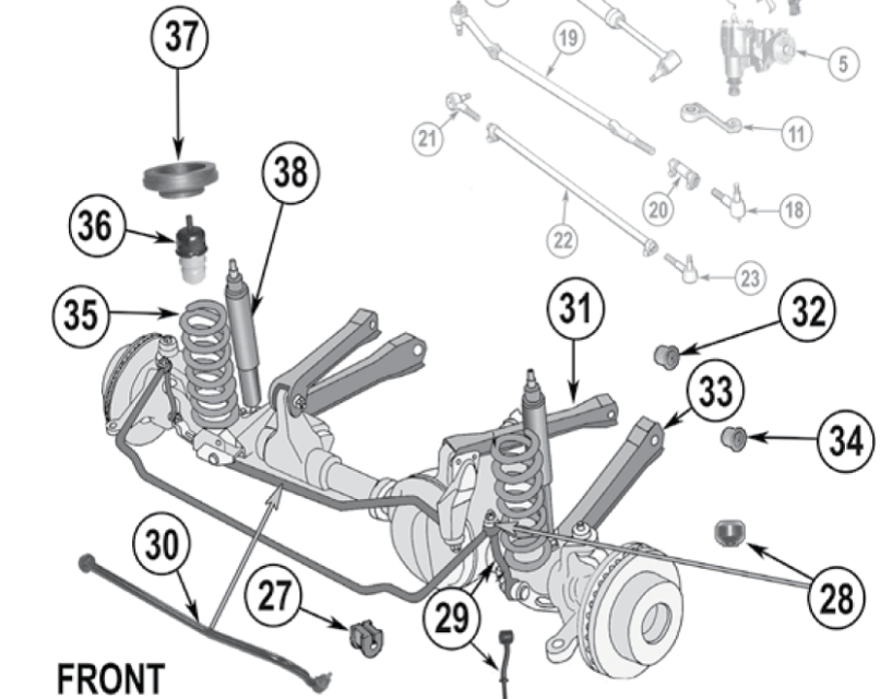
Let's dive deep into the 2004 Jeep Grand Cherokee's front suspension. Understanding its intricacies is crucial for diagnosing problems, performing repairs, and even planning modifications. This isn't just about turning wrenches; it's about knowing what makes your Jeep tick. Having a clear grasp of the front suspension layout is invaluable for any serious DIY enthusiast or mechanic.
Purpose of the Front Suspension Diagram
A front suspension diagram serves as a roadmap to understanding the complex system supporting your 2004 Grand Cherokee's front end. It allows you to:
- Identify components: Quickly locate and identify all parts of the front suspension assembly.
- Understand relationships: See how the parts interact with each other.
- Troubleshoot issues: Pinpoint the source of suspension problems like noises, uneven tire wear, or poor handling.
- Plan repairs and replacements: Determine the necessary parts and procedures for specific tasks.
- Perform modifications: Understand the impact of lift kits, upgraded shocks, or other aftermarket parts.
Essentially, the diagram turns a complicated assembly into an understandable visual representation. We have a high-resolution version of the 2004 Jeep Grand Cherokee front suspension diagram available for download at the end of this article, which will make this explanation even easier to follow.
Key Specs and Main Parts of the 2004 Grand Cherokee WJ Front Suspension
The 2004 Grand Cherokee WJ utilizes a solid axle front suspension with a five-link coil spring design. This provides a good balance of off-road capability and on-road comfort.
Main Components:
- Solid Front Axle: A rigid beam connecting the front wheels, allowing them to move in unison. This is central to the Jeep's off-road prowess.
- Coil Springs: These springs provide the primary suspension, absorbing bumps and supporting the vehicle's weight. Their spring rate is crucial for ride quality and load-carrying capacity.
- Shock Absorbers: Dampen the oscillations of the springs, preventing the vehicle from bouncing excessively. Look for terms like rebound and compression when considering aftermarket shocks.
- Upper Control Arms (Two): These arms connect the axle to the vehicle's frame and control the axle's lateral movement.
- Lower Control Arms (Two): Similar to the upper control arms but located lower on the axle and frame. They contribute to axle stability and wheel alignment.
- Track Bar (Panhard Rod): A diagonal bar that connects the axle to the frame. This centers the axle under the vehicle and prevents lateral movement during suspension articulation. Its length and angle are critical for proper handling, especially after lift modifications.
- Sway Bar (Anti-Roll Bar): Connects the left and right sides of the suspension to reduce body roll during cornering. Disconnecting it (if equipped with quick disconnects) improves articulation off-road.
- Sway Bar Links: Connect the sway bar to the axle. These links are often a point of failure, especially with lifted vehicles.
- Steering Knuckles (Unit Bearings): The mounting point for the wheel hubs, brakes, and steering components.
- Tie Rods and Drag Link: Part of the steering system, connecting the steering box to the steering knuckles to allow the driver to steer the vehicle.
- Bushings: Rubber or polyurethane components that dampen vibrations and allow for controlled movement between suspension parts. Worn bushings can cause sloppy handling and noise.
Key Specs: It's important to know your vehicle's factory ride height and alignment specifications. These can be found in your owner's manual or a service manual. Knowing the stock specifications is crucial when diagnosing suspension issues or planning modifications.
Understanding Symbols in the Diagram
Suspension diagrams use a standard set of symbols to represent different components. Here's a general guide:
- Solid Lines: Typically represent solid parts like control arms, the axle housing, or the frame.
- Dashed Lines: Can represent hidden components, lines indicating movement paths, or reference lines.
- Hatched Areas: Often indicate a cutaway view, showing the internal structure of a component.
- Circles and Arcs: May represent pivots, joints, or bushing locations.
- Arrows: Usually indicate direction of force, movement, or flow (e.g., in hydraulic systems).
- Color Coding: Some diagrams use color to differentiate between different systems (e.g., steering vs. suspension) or materials. Consult the diagram's legend for specific color meanings.
The diagram we offer for download will contain a detailed legend explaining all symbols used.
How the Front Suspension Works
The 2004 Grand Cherokee's front suspension is designed to perform several critical functions:
- Supporting Vehicle Weight: The coil springs bear the weight of the vehicle, preventing the chassis from resting directly on the axle.
- Absorbing Impacts: When the wheels encounter bumps, the springs compress, absorbing the energy of the impact.
- Damping Oscillations: The shock absorbers dampen the spring's oscillations, preventing excessive bouncing and maintaining tire contact with the road.
- Controlling Axle Movement: The control arms and track bar work together to control the axle's movement, keeping it centered under the vehicle and preventing unwanted lateral movement.
- Maintaining Wheel Alignment: The geometry of the suspension components ensures that the wheels maintain proper alignment angles (caster, camber, toe) for optimal handling and tire wear.
- Reducing Body Roll: The sway bar helps to minimize body roll during cornering, improving stability and handling.
The five-link design is crucial for articulation off-road. Each link is a suspension arm that connects the axle to the frame. The control arms control fore and aft movement, while the track bar controls lateral movement. This separation of functions allows for better articulation and ride quality compared to simpler suspension designs.
Real-World Use: Basic Troubleshooting Tips
Understanding the front suspension diagram is immensely helpful when troubleshooting suspension problems. Here are a few common issues and how the diagram can assist:
- Clunking Noise: Could indicate worn bushings in the control arms, track bar, or sway bar links. The diagram helps you locate these bushings for inspection.
- Wandering Steering: Could be caused by worn tie rod ends, ball joints, or a loose track bar. The diagram shows the location and connections of these steering components.
- Uneven Tire Wear: Often indicates misalignment issues. The diagram doesn't directly address alignment, but knowing the component locations helps you visualize how changes in suspension height or worn parts can affect alignment angles.
- Excessive Body Roll: Likely a problem with the sway bar or its links. The diagram makes it easy to inspect these components for damage or looseness.
- Bouncing or Poor Ride Quality: Could be due to worn shocks or damaged coil springs. The diagram helps you locate and inspect these components.
When troubleshooting, always start with a visual inspection. Use the diagram to guide your inspection, paying close attention to bushings, joints, and mounting points. Check for cracks, tears, looseness, or signs of wear.
Safety Considerations
Working on the front suspension involves potential hazards. Always prioritize safety:
- Spring Compression: Coil springs store a tremendous amount of energy. Never attempt to remove or compress a coil spring without using a proper spring compressor. Improper spring compression can result in serious injury or death.
- Jack Stands: Always use high-quality jack stands to support the vehicle when working underneath. Never rely solely on a jack.
- Wheel Chocks: Use wheel chocks to prevent the vehicle from rolling while it's lifted.
- Torque Specifications: Always tighten suspension components to the manufacturer's specified torque. Improperly tightened bolts can lead to component failure.
- Brake Lines: Be careful not to damage brake lines when working on the suspension. Damaged brake lines can result in brake failure.
- ABS Sensors: The ABS sensors can be easily damaged. When replacing unit bearings/hubs, use extra care not to damage this component.
The suspension components are highly stressed parts. Never reuse bolts that are designed to be replaced during service. Torque specifications are critical on suspension parts. If unsure of torque specification consult a service manual.
By understanding the 2004 Jeep Grand Cherokee's front suspension diagram and following proper safety procedures, you can confidently tackle many suspension-related tasks. Remember to always consult a qualified mechanic if you're unsure about any procedure.
To help you get started on your project, we've made the high-resolution front suspension diagram available for download. Please be safe and take your time to properly diagnose and repair.
[Download Link Here]