2004 Jeep Grand Cherokee Wiring Diagram Pdf
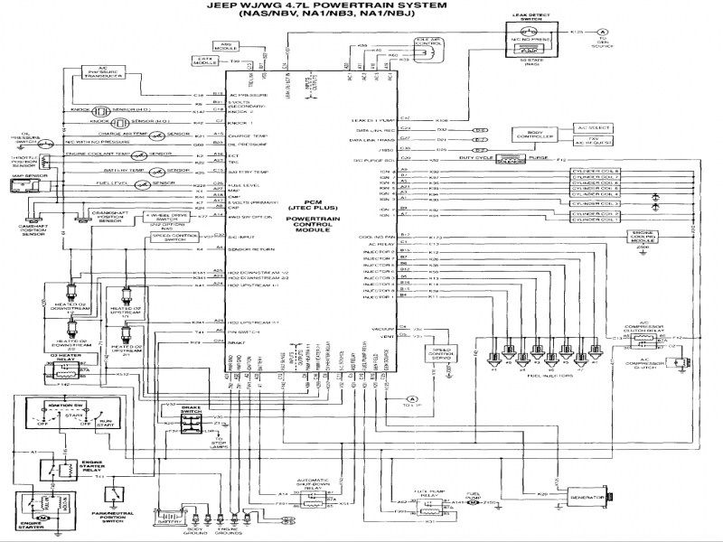
The 2004 Jeep Grand Cherokee (WJ/WG) is a robust SUV, but like any vehicle of its age, understanding its electrical system is crucial for proper maintenance, repairs, and even modifications. A reliable wiring diagram is your best friend for navigating the complexities of the Jeep's electrical network. Specifically, the 2004 Jeep Grand Cherokee Wiring Diagram PDF offers a comprehensive visual representation of all the electrical circuits and components, making troubleshooting and repairs significantly easier.
Purpose of the 2004 Jeep Grand Cherokee Wiring Diagram
Why bother with a wiring diagram? The primary purpose is to provide a roadmap for the vehicle's electrical system. This is invaluable for several reasons:
- Troubleshooting: When an electrical component fails, the diagram allows you to trace the circuit, pinpoint the fault, and identify potential causes (short circuits, open circuits, faulty relays, etc.).
- Repairing: The diagram guides you in correctly connecting replacement parts, ensuring that everything is wired according to the manufacturer's specifications.
- Modifying: If you're adding aftermarket accessories like lights, stereos, or remote starters, the diagram allows you to integrate them into the existing electrical system safely and effectively. Properly tapping into the correct power and ground points is crucial for preventing damage.
- Understanding: Even if you don't plan on doing any repairs yourself, studying the diagram can give you a better understanding of how the various electrical systems work in your Jeep.
Key Specs and Main Parts of the Electrical System
The 2004 Jeep Grand Cherokee features a complex electrical system that includes several key components. Understanding these components will make using the wiring diagram much easier. Some main parts include:
- Power Distribution Center (PDC): This is the central hub for fuses and relays, distributing power to various circuits. The PDC is usually located under the hood.
- Central Timer Module (CTM): The CTM controls various timed functions, such as interior lights, wipers, and power windows.
- Powertrain Control Module (PCM): This computer controls the engine and transmission, relying heavily on sensor inputs and controlling actuators based on pre-programmed logic.
- Body Control Module (BCM): Manages various body-related functions like door locks, security system, and exterior lighting.
- Sensors: A vast array of sensors provides data to the PCM, BCM, and other modules, including temperature sensors, pressure sensors, speed sensors, and position sensors.
- Actuators: These are the devices that the control modules command to perform actions, such as fuel injectors, relays, solenoids, and motors.
- Wiring Harnesses: The vast network of wires that connect all of these components together, grouped into harnesses for organization and protection.
Key specifications to keep in mind might be wire gauge (thickness, impacting current carrying capacity) and voltage ratings. The system is primarily 12V DC, but knowing which circuits have higher amperage requirements (like the starter motor) is essential.
Understanding Wiring Diagram Symbols
A wiring diagram is a symbolic representation of the electrical system, and learning the symbols is essential to interpreting the diagram correctly. Here's a breakdown of common symbols:
- Lines: Lines represent wires. Thicker lines typically indicate higher current carrying capacity. Dotted or dashed lines often represent shielded cables or data communication lines (like those used in the CAN bus network).
- Colors: Each wire is assigned a color code, indicated on the diagram with abbreviations (e.g., BK for black, RD for red, VT for violet, GY for gray). The wiring diagram includes a color code chart to help you decode the wire colors.
- Components:
- Resistors: Zigzag line.
- Capacitors: Two parallel lines.
- Inductors: Series of curved lines.
- Relays: A coil symbol and a switch symbol showing the contacts.
- Fuses: A line with a smaller line cutting through it.
- Ground: Various symbols representing connection to the vehicle's chassis ground.
- Switches: A line representing the contact and another line representing the switch position.
- Junctions: A dot where wires connect. If wires cross without a dot, it means they are not connected.
Note: The specific symbols used can vary slightly between different diagrams, so always refer to the legend provided with the 2004 Jeep Grand Cherokee Wiring Diagram PDF.
How It Works: Circuit Tracing
Let's say your headlights aren't working. Here's how you might use the wiring diagram to troubleshoot:
- Locate the Headlight Circuit: Find the section of the diagram that shows the headlight circuit. This will include the headlight switch, fuses, relays, wiring, and the headlights themselves.
- Trace the Power Flow: Start at the power source (typically the battery), follow the circuit through the fuse, headlight switch, relay (if present), and finally to the headlights.
- Identify Potential Fault Points: Look for potential points of failure along the circuit. For example, check the fuse with a multimeter to see if it's blown. If the fuse is good, check the headlight switch to see if it's functioning correctly. You can use a multimeter to check for voltage at various points along the circuit.
- Check the Ground Connection: A bad ground can also cause the headlights to fail. Use the wiring diagram to locate the ground point for the headlights and ensure it's clean and secure.
By systematically tracing the circuit, you can narrow down the possible causes of the problem and pinpoint the exact component that needs to be replaced.
Real-World Use: Basic Troubleshooting Tips
Here are some practical troubleshooting tips when using the wiring diagram:
- Start Simple: Before diving into complex troubleshooting, check the obvious things first, like fuses and bulbs.
- Use a Multimeter: A multimeter is an essential tool for electrical troubleshooting. It allows you to measure voltage, current, and resistance, helping you identify shorts, opens, and voltage drops.
- Check Ground Connections: Poor ground connections are a common cause of electrical problems. Make sure all ground connections are clean and secure.
- Be Methodical: Follow the wiring diagram systematically, testing each component and connection along the circuit.
- Consult Service Bulletins: Check for any technical service bulletins (TSBs) related to the specific problem you're experiencing. These bulletins often provide valuable information about common issues and their solutions.
Safety Considerations
Working with electrical systems can be dangerous. Here are some safety precautions to keep in mind:
- Disconnect the Battery: Always disconnect the negative battery cable before working on any electrical component. This will prevent accidental short circuits and electric shocks.
- Work in a Well-Ventilated Area: Some electrical components can produce harmful fumes when heated.
- Use Insulated Tools: Use tools with insulated handles to protect yourself from electric shock.
- Avoid Water: Never work on electrical systems in wet conditions.
- High Voltage Components: Be especially cautious around the ignition system (coil packs, spark plugs), as these components can generate very high voltages, even with the battery disconnected. Discharge the capacitors in the ignition system before working on it.
- Airbag Systems: Exercise extreme caution when working near the airbag system. Improper handling of airbags can result in serious injury. If you're unsure about working on the airbag system, consult a qualified technician.
By following these safety precautions, you can minimize the risk of injury while working on your Jeep's electrical system.
We have the 2004 Jeep Grand Cherokee Wiring Diagram PDF file available for download. With it, you'll have the key to unlocking your Jeep's electrical mysteries and tackling repairs with confidence.