
2004 Mustang Fuse Box Diagram Under Dash
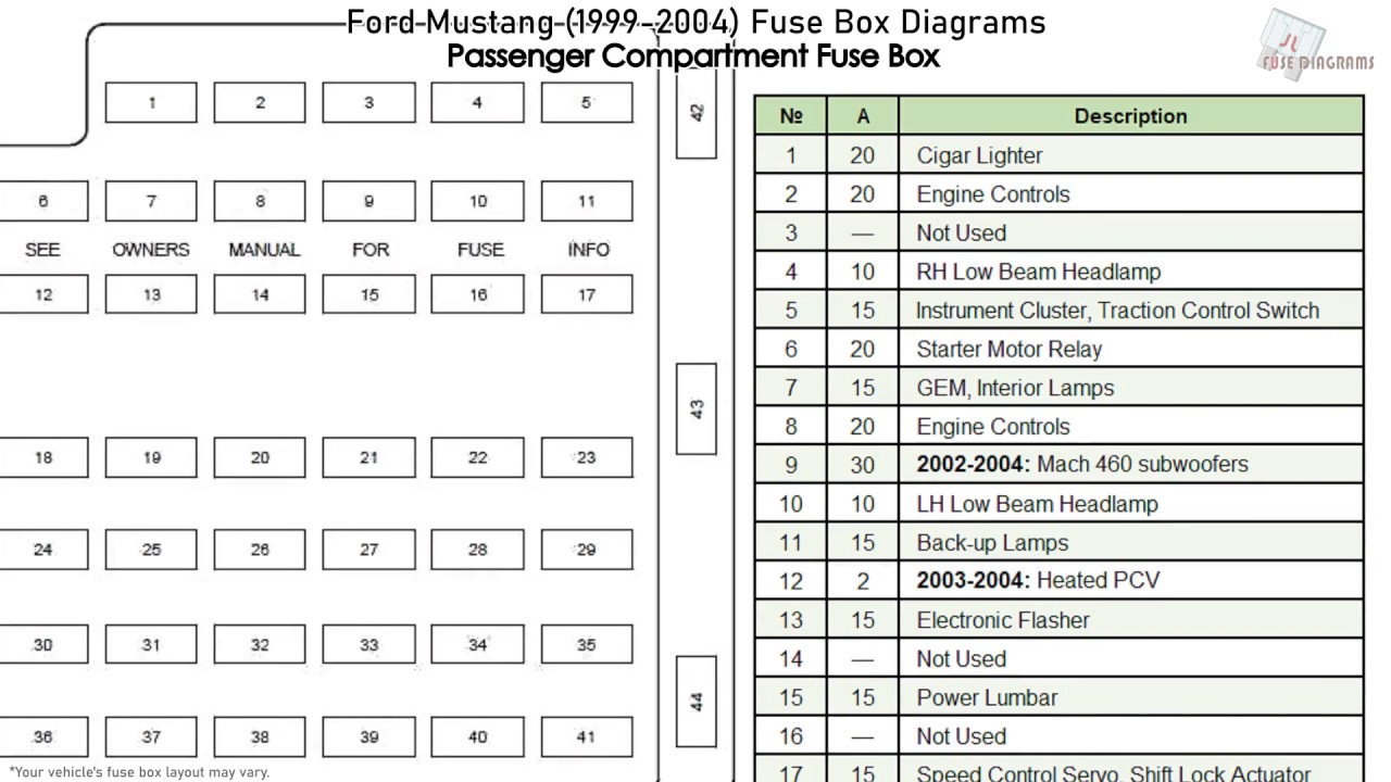
For the intermediate DIY enthusiast tackling electrical issues or planning modifications on a 2004 Ford Mustang, a solid understanding of the under-dash fuse box is absolutely essential. This isn't just about replacing a blown fuse; it's about safely navigating the car's intricate electrical system, preventing further damage, and confidently undertaking modifications. This guide will walk you through the 2004 Mustang's under-dash fuse box diagram, empowering you to diagnose, repair, and upgrade with precision.
Purpose of Understanding the Fuse Box Diagram
Why bother understanding a fuse box diagram? Here are a few compelling reasons:
- Troubleshooting Electrical Issues: When a component stops working (lights, radio, wipers, etc.), the fuse box is the first place to look. The diagram allows you to pinpoint the fuse responsible for that specific circuit.
- Performing Repairs: Replacing a blown fuse is a simple fix, but understanding the circuit it protects is crucial. If a fuse blows repeatedly, it indicates a larger problem requiring further investigation, preventing potential short circuits.
- Modifications and Upgrades: Adding aftermarket accessories (lights, stereo systems, etc.) requires tapping into the existing electrical system. Knowing the fuse box layout is vital for safely and correctly integrating these new components and choosing suitable power sources.
- Preventing Damage: Incorrectly replacing a fuse with one of a higher amperage rating can overload the circuit, potentially damaging wiring and electronic components. The diagram ensures you use the correct fuse type.
- General Knowledge: Understanding your vehicle's electrical system empowers you to be a more informed and capable car owner.
Key Specs and Main Parts
The under-dash fuse box, officially known as the Central Junction Box (CJB), is located, unsurprisingly, under the dashboard on the driver's side. You'll typically find it behind a removable access panel. The 2004 Mustang's CJB houses several crucial components:
- Fuses: These are the sacrificial elements designed to protect circuits from overcurrent. They come in various amperage ratings, indicated by numbers printed on the fuse itself (e.g., 5A, 10A, 20A). Common fuse types include blade fuses (also known as spade fuses) and, less commonly in the CJB, cartridge fuses.
- Relays: Relays are electromagnetic switches that allow a low-current circuit to control a high-current circuit. For example, the headlight relay uses a small signal from the headlight switch to activate the high-current circuit that powers the headlights.
- Fuse Box Housing: This is the physical container that holds the fuses and relays, providing a secure and organized environment.
- Fuse Box Cover/Diagram: Usually, a label on the inside of the fuse box cover provides a diagram indicating the function and amperage rating of each fuse and relay. This is what we're discussing here and will be a primary source.
- Connectors and Wiring Harness: These provide the electrical connections to the fuse box from the car's main wiring loom.
Understanding Symbols and Diagram Conventions
The fuse box diagram uses specific symbols and conventions to convey information efficiently. Here's a breakdown:
- Lines: Solid lines generally represent electrical circuits, indicating the path of current flow. Thicker lines might indicate circuits carrying higher amperage.
- Colors: Wire colors are often indicated next to the circuit lines in the diagram. Common colors include red (often for power), black (often for ground), and various other colors for specific circuits. Note that wire color can vary *slightly* between vehicles, even of the same model year, due to manufacturing variances.
- Fuse Symbols: Fuses are typically represented by a rectangular or square symbol with a line running through it. The amperage rating is usually noted next to the symbol.
- Relay Symbols: Relays are represented by a square or rectangular symbol with internal components depicting the coil and switch contacts. The diagram will indicate the relay's function (e.g., Headlight Relay, Fuel Pump Relay).
- Component Labels: Each fuse and relay position is labeled with a description of the component or system it protects or controls (e.g., "Radio," "Wipers," "Fuel Pump").
- Ground Symbols: A symbol resembling an upside-down tree or a series of descending lines indicates a ground connection, where the circuit is connected to the vehicle's chassis, providing a return path for the current.
- Connector Symbols: Where wiring harnesses plug into the fuse box there are corresponding symbols in the diagram. These usually look like squares with arrows pointing into it.
How It Works: Electrical Circuit Protection
The fuse box serves as the central distribution and protection point for the vehicle's electrical system. Each fuse is connected in series with a specific circuit. When the current in that circuit exceeds the fuse's amperage rating, the fuse's internal element melts, breaking the circuit and preventing excessive current from flowing and potentially damaging sensitive components. Relays, on the other hand, enable low-current circuits to switch larger loads. The control circuit sends a small current to the relay's coil, which energizes an electromagnet. This electromagnet then pulls a switch closed, completing a high-current circuit that powers the desired component.
Real-World Use: Basic Troubleshooting Tips
Here are some basic troubleshooting tips using the fuse box diagram:
- Component Failure: If a component stops working, consult the fuse box diagram to identify the corresponding fuse. Check the fuse for continuity using a multimeter (set to the ohms or continuity setting). If the fuse is blown (no continuity), replace it with a fuse of the same amperage rating.
- Repeated Fuse Blowing: If a fuse blows repeatedly, it indicates a short circuit or an overload in the circuit. Do not simply replace the fuse with a higher amperage fuse. This is a fire hazard. Inspect the wiring and components connected to the circuit for damage or shorts. This will require more in-depth diagnostic procedures using a wiring diagram and a multimeter.
- Voltage Drop Testing: To check the health of a circuit that may be experiencing reduced power, a technician may use voltage drop testing techniques. The fuse box diagram is useful in finding key test points that can be used to check voltage as current passes thru the circuit.
- Accessory Installation: When installing aftermarket accessories, use the fuse box diagram to identify a suitable power source. Use an add-a-circuit fuse tap to safely tap into an existing circuit without cutting or splicing wires. Ensure that the circuit you tap into can handle the additional current draw of the new accessory.
Safety Precautions
Working with electrical systems can be dangerous. Here are some important safety precautions:
- Disconnect the Battery: Before working on the fuse box, disconnect the negative (black) terminal of the battery to prevent accidental short circuits.
- Use the Correct Fuse: Always replace a blown fuse with a fuse of the same amperage rating. Using a higher amperage fuse can overload the circuit and cause damage or a fire.
- Inspect for Damage: Before replacing a fuse, inspect the fuse box and wiring for any signs of damage, such as melted plastic, corrosion, or frayed wires.
- Be Aware of Airbag Circuits: The airbag system is a sensitive and potentially dangerous system. Avoid tampering with fuses and wiring related to the airbag system. If you suspect an airbag system malfunction, consult a qualified technician.
- Avoid Working in Wet Conditions: Never work on the electrical system in wet or damp conditions.
The airbag control module (ACM) and related circuitry can be particularly dangerous. Mishandling these components can lead to accidental airbag deployment, causing serious injury. If you are uncomfortable working with these systems, it's best to consult a qualified mechanic.
Understanding the 2004 Mustang's under-dash fuse box diagram is a valuable skill for any DIY mechanic or car enthusiast. By carefully studying the diagram and following proper safety precautions, you can confidently troubleshoot electrical issues, perform repairs, and safely add aftermarket accessories to your Mustang. Armed with this knowledge, you can maintain and modify your vehicle with greater confidence and expertise.
We have the 2004 Mustang Under Dash Fuse Box Diagram available for download. This comprehensive resource will provide you with a detailed visual guide to your vehicle's electrical system, allowing you to diagnose and address issues with accuracy and confidence.