2004 Nissan Maxima Fuse Box Diagram
For the experienced DIY enthusiast tackling electrical issues on a 2004 Nissan Maxima, a reliable fuse box diagram is an absolutely essential tool. Whether you're diagnosing a blown fuse, installing aftermarket accessories, or simply trying to understand your car's electrical system, this diagram provides a roadmap to navigate the intricate web of circuits and components. This guide will walk you through understanding the 2004 Maxima's fuse box diagram, providing the knowledge needed for effective troubleshooting and repairs.
Purpose of a Fuse Box Diagram
The fuse box diagram serves several critical purposes:
- Troubleshooting Electrical Problems: When an electrical component malfunctions, a blown fuse is often the culprit. The diagram pinpoints which fuse controls that specific circuit, saving you time and frustration.
- Installing Aftermarket Accessories: Safely tapping into the electrical system for accessories like aftermarket stereos, lighting, or alarms requires knowing which circuits are available and appropriately rated.
- Understanding the Electrical System: The diagram offers a visual representation of how the various electrical components are connected and protected, enhancing your understanding of the overall system.
- Preventing Damage: Replacing a blown fuse with the wrong amperage can lead to serious damage to the electrical system, potentially causing a fire. The diagram ensures you use the correct fuse rating.
Key Specs and Main Parts of the 2004 Maxima Fuse Box
The 2004 Nissan Maxima typically has two main fuse box locations:
- Interior Fuse Box: Located inside the cabin, often under the dashboard on the driver's side (though some models might place it on the passenger side). This box typically houses fuses for interior components like the radio, lights, power windows, and climate control.
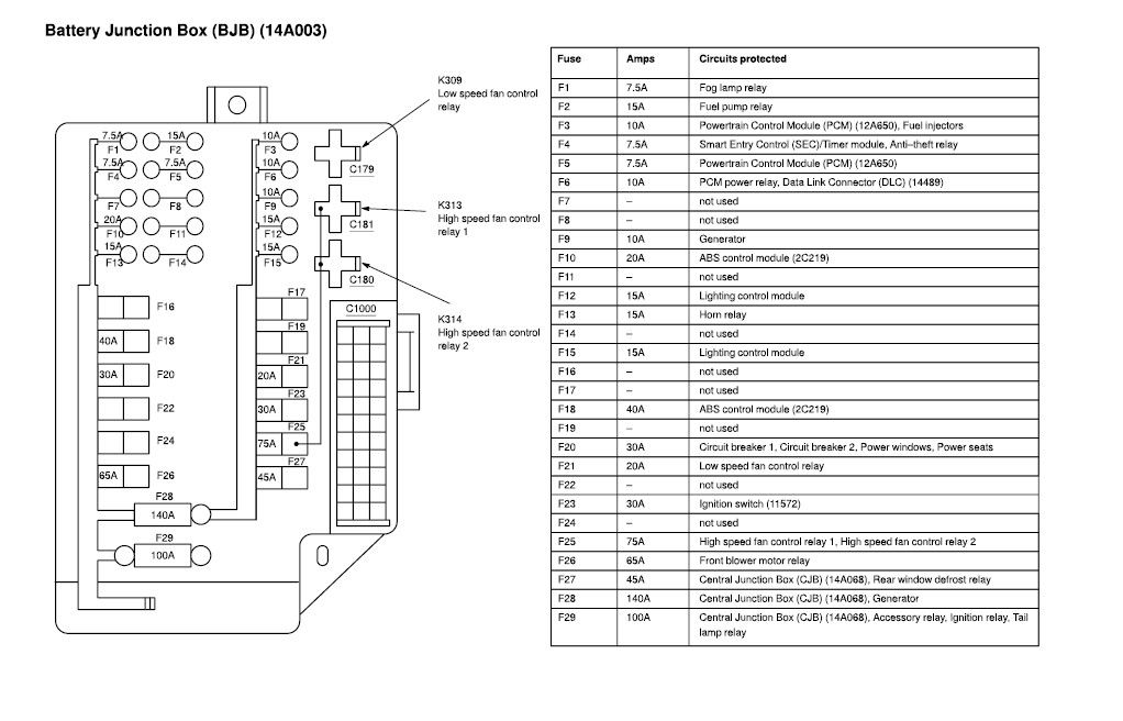
- Engine Compartment Fuse Box: Situated in the engine bay, usually near the battery or on the fender. This box contains fuses for critical engine and drivetrain components like the fuel pump, ignition system, and starter motor. Some larger circuits (high amperage) are protected with fusible links in this location as well.
Key Specs to consider:
- Fuse Amperage Ratings: Fuses are rated in amperes (amps), indicating the maximum current they can handle before blowing. Common ratings include 5A, 7.5A, 10A, 15A, 20A, 25A, and 30A. Using a fuse with a higher amperage rating than specified can overload the circuit and cause damage.
- Fuse Types: The 2004 Maxima primarily uses blade-type fuses, also known as ATO or APR fuses. These are easy to identify by their plastic body and exposed metal prongs.
- Fusible Links: Located in the engine bay, fusible links are essentially heavy-duty fuses designed to protect high-current circuits like the battery charging system. They look like short lengths of wire encased in a protective covering.
- Relays: Relays are electromechanical switches that allow a low-current circuit to control a high-current circuit. They are often used to power components like the headlights, fuel pump, and starter motor. The fuse diagram doesn't always show relay locations, but often the relay location will be shown in the owner’s manual.
Understanding Fuse Box Diagram Symbols
Fuse box diagrams employ a standardized set of symbols and conventions:
- Lines: Lines represent electrical wires or circuits. The thickness of the line sometimes indicates the wire gauge (thicker lines for higher current circuits).
- Boxes: Boxes typically represent fuses or relays. The amperage rating of a fuse is usually printed directly on the fuse itself and indicated on the diagram.
- Circles: Circles often represent connectors or junctions where wires are joined.
- Icons: Icons are used to represent the electrical component being protected by a particular fuse. For example, a light bulb icon indicates the fuse protects the lighting circuit, a radio icon indicates the fuse protects the audio system, and so on. The legend of the fusebox diagram is very important here to understand which icons represent which components.
- Colors: Wire colors are often indicated on the diagram using abbreviations (e.g., "BLU" for blue, "RED" for red, "BLK" for black). Matching wire colors when troubleshooting or wiring aftermarket accessories is crucial to avoid short circuits.
Important Considerations: Different versions of the 2004 Maxima (e.g., different trim levels or those sold in different regions) might have slightly different fuse box layouts. Always consult the diagram specific to your vehicle’s VIN.
How the Fuse Box Works
The fuse box acts as the central distribution point and protection mechanism for your car's electrical system. Each fuse is a sacrificial element designed to break the circuit if the current exceeds its rated amperage. This protects the wiring and components downstream from damage caused by short circuits, overloads, or malfunctions.
When an electrical component fails, it often draws excessive current. This overcurrent heats up the fuse's internal element, causing it to melt and break the circuit. This prevents further damage and potentially a fire. Identifying the blown fuse using the diagram allows you to quickly isolate the problem and replace the faulty fuse.
Real-World Use: Basic Troubleshooting Tips
Here’s a step-by-step approach to troubleshooting electrical problems using the fuse box diagram:
- Identify the Problem: Determine which electrical component is malfunctioning.
- Locate the Fuse Box: Find the relevant fuse box (interior or engine compartment).
- Consult the Diagram: Refer to the fuse box diagram to identify the fuse that protects the malfunctioning component.
- Inspect the Fuse: Visually inspect the fuse. A blown fuse will typically have a broken filament (the thin wire inside the fuse). Some fuses are see-through so it's easy to inspect.
- Test the Fuse (Recommended): Use a multimeter to test the fuse for continuity. Set the multimeter to the continuity setting (often indicated by a speaker symbol). Place the probes on either side of the fuse. If the multimeter beeps or shows a low resistance reading, the fuse is good. If there is no continuity (no beep or a high resistance reading), the fuse is blown.
- Replace the Fuse: Replace the blown fuse with a new fuse of the exact same amperage rating. Using a higher amperage fuse can be dangerous.
- Test the Component: Turn on the component to see if it now works.
- If the Fuse Blows Again: If the new fuse blows immediately, it indicates a more serious problem in the circuit, such as a short circuit or a faulty component. Further diagnostics are required. Do not keep replacing fuses without finding the root cause!
Safety Considerations
Working with electrical systems can be dangerous. Here are some important safety precautions:
- Disconnect the Battery: Before working on any electrical components, disconnect the negative (-) battery terminal to prevent accidental short circuits.
- Use Proper Tools: Use insulated tools to avoid electric shock.
- Never Exceed the Fuse Rating: Always replace a blown fuse with one of the correct amperage rating. Using a higher amperage fuse can overload the circuit and cause a fire.
- Be Careful Around High-Voltage Components: Components like the ignition system and the alternator can carry high voltages even with the battery disconnected. Exercise extreme caution when working near these components.
- Avoid Water: Never work on the electrical system in wet conditions.
Special Note: The airbag system is a very sensitive and potentially dangerous component. If you suspect a problem with the airbag system, consult a qualified technician. Tampering with the airbag system can result in accidental deployment, causing serious injury.
By carefully studying the 2004 Nissan Maxima fuse box diagram and following these guidelines, you can confidently tackle many common electrical issues and gain a deeper understanding of your car's electrical system.
For a downloadable copy of the 2004 Nissan Maxima Fuse Box Diagram, please contact us.