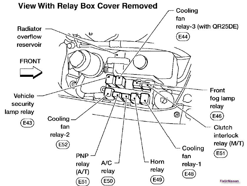
2004 Nissan Sentra Relay Box Diagram
Let's dive into the relay box diagram for your 2004 Nissan Sentra. Having a solid understanding of this diagram is crucial for anyone looking to diagnose electrical issues, perform modifications, or simply understand the inner workings of their vehicle's electrical system. Think of it as a roadmap for your Sentra's electronic nervous system.
Purpose of the 2004 Nissan Sentra Relay Box Diagram
The relay box diagram serves several vital purposes:
- Troubleshooting Electrical Problems: When a component malfunctions – say, your headlights won't turn on, or the horn refuses to honk – the diagram helps you trace the circuit back to its power source and identify potential points of failure, such as a blown fuse or a faulty relay.
- Performing Modifications: If you're adding aftermarket accessories like fog lights, a new stereo system, or an alarm, the diagram shows you where to safely tap into the existing electrical system and how to properly fuse your new circuits.
- General Understanding: Even if you're not currently facing any issues, studying the diagram can give you a deeper understanding of how your car's various electrical systems interact, making you a more informed car owner.
- Repairing Damaged Wiring: Accidents happen. Wires can get cut, frayed, or damaged. The diagram helps you identify the correct wiring paths for repairs and splices.
Key Specs and Main Parts
The 2004 Nissan Sentra, like most vehicles, uses a relay box to consolidate and protect its electrical circuits. Understanding the key components within the relay box is essential for using the diagram effectively.
Main Components:
- Relays: These are electromechanical switches that allow a low-current circuit to control a high-current circuit. Think of them as electrically operated amplifiers. They protect delicate switches from the heavy loads of components like headlights and the starter motor. Relays consist of a coil, a common terminal, a normally open (NO) terminal, and a normally closed (NC) terminal. When the coil is energized, it creates a magnetic field that pulls the common terminal away from the NC terminal and onto the NO terminal, completing the high-current circuit.
- Fuses: These are safety devices designed to protect circuits from overcurrent. They contain a thin wire that melts and breaks the circuit if the current exceeds a certain limit. Fuses are rated in Amperes (Amps), indicating the amount of current they can handle before blowing.
- Circuit Breakers: Similar to fuses, but resettable. Instead of melting, a circuit breaker trips when overloaded, opening the circuit. You can then reset it after the fault is corrected. They are less common in older vehicles like the 2004 Sentra, but they can be present in certain circuits.
- Wiring Harness: This is the organized bundle of wires that connects all the electrical components. The diagram shows how these wires are routed throughout the vehicle.
- Connectors: These are the plugs and sockets that connect the wiring harness to various components. The diagram often identifies the pin numbers within the connectors, which is crucial for testing and troubleshooting.
Typical Locations: The primary relay box is typically found under the hood, near the battery. There may also be a secondary relay/fuse box located inside the cabin, often under the dashboard or behind the glove compartment.
Understanding the Symbols
Relay box diagrams use a standardized set of symbols to represent different electrical components and connections. Learning to interpret these symbols is key to understanding the diagram.
Common Symbols:
- Solid Lines: Represent wires. The thickness of the line doesn't necessarily indicate wire gauge, but it may be used to distinguish between power and ground wires on some diagrams.
- Dashed Lines: Often represent ground connections or connections to the vehicle's chassis.
- Fuse Symbol: A wavy line inside a rectangle. The Amp rating is usually indicated next to the symbol.
- Relay Symbol: A coil symbol connected to a switch symbol. The switch symbol shows the normally open (NO) and normally closed (NC) contacts.
- Ground Symbol: Typically represented by a series of downward-pointing triangles.
- Connector Symbol: Usually a circle or square with lines extending from it, indicating the wires connected to that pin. Pin numbers are usually indicated near the connector symbol.
- Colors: Wires are often color-coded in the diagram, and this corresponds to the actual wire colors in the vehicle. For example, a blue wire is usually indicated by "BLU" or a similar abbreviation.
Important Note: Not all diagrams are created equal. Some are more detailed than others. The OEM (Original Equipment Manufacturer) diagram from Nissan is usually the most accurate and comprehensive. Aftermarket diagrams may simplify certain aspects, but they can still be useful.
How It Works: Following the Circuit
The key to using a relay box diagram is to trace the flow of electricity through the circuit you're investigating. Start with the power source (usually the battery) and follow the circuit through the fuse, relay (if applicable), switch, and finally to the component being powered. For example, to trace the headlight circuit:
- Find the headlight fuse in the diagram.
- Note the fuse's Amp rating.
- Follow the wire from the fuse to the headlight relay (if there is one).
- Trace the relay's control circuit back to the headlight switch.
- Finally, follow the wire from the relay to the headlight bulb.
By carefully following the circuit, you can identify potential points of failure. If the fuse is blown, the problem could be an overcurrent in the headlight circuit. If the relay is faulty, the headlights may not turn on even if the fuse is good. If the wiring is damaged, the circuit may be incomplete.
Real-World Use: Basic Troubleshooting
Here are some basic troubleshooting tips using the relay box diagram:
- Symptom: Headlights not working.
- Possible Causes: Blown headlight fuse, faulty headlight relay, bad headlight switch, burned-out headlight bulbs, damaged wiring.
- Troubleshooting Steps:
- Check the headlight fuse using the diagram to locate it. Replace if blown.
- If the fuse is good, check the headlight relay. You can try swapping it with a known-good relay (of the same type) to see if that fixes the problem.
- If the relay is good, check the headlight switch. Use a multimeter to test its continuity.
- Inspect the wiring for any damage or loose connections.
- Symptom: Car won't start.
- Possible Causes: Dead battery, faulty starter relay, bad starter motor, faulty ignition switch.
- Troubleshooting Steps:
- Check the battery voltage. It should be at least 12.6 volts.
- Check the starter relay. Use the diagram to locate it. You can try tapping on the relay while someone tries to start the car. If it starts, the relay is likely faulty.
- If the relay is good, check the starter motor. You can try bypassing the relay and directly powering the starter motor with a jumper cable. (Be very careful doing this!)
- Check the ignition switch. Use a multimeter to test its continuity.
Safety Precautions
Working with electrical systems can be dangerous. Always take the following precautions:
- Disconnect the Battery: Before working on any electrical circuit, disconnect the negative (-) terminal of the battery to prevent short circuits and electrical shocks.
- Use Proper Tools: Use insulated tools to avoid electrical shocks.
- Avoid Water: Never work on electrical systems in wet conditions.
- Be Careful with Airbags: If you're working near the airbag system, be extremely careful. Follow the manufacturer's instructions for disabling the airbag system before working on it. Accidental deployment of an airbag can cause serious injury.
- Fuses: Never replace a fuse with a higher amperage fuse. This can overload the circuit and cause a fire. Always use the correct amperage fuse as specified in the diagram.
- Capacitors: Be aware that some components, like those in the audio system, can store electrical charge even after the battery is disconnected. Discharge these capacitors before working on them.
Specifically regarding relays and fuses, remember that incorrect handling or modification of these components can lead to electrical fires and damage to your vehicle. Always consult the diagram and follow safe practices.
Now that you have a better understanding of the 2004 Nissan Sentra's relay box diagram, you're well-equipped to diagnose and repair electrical issues in your vehicle. Remember to always prioritize safety and consult with a qualified mechanic if you're unsure about any procedure.
We have the full resolution file diagram available for download. Click here to download the diagram file.