2004 Nissan Titan Fuse Box Diagram
Understanding your vehicle's electrical system is crucial for both routine maintenance and tackling more complex repairs. For 2004 Nissan Titan owners, having a clear and accurate fuse box diagram is an indispensable tool. This article serves as a comprehensive guide to the 2004 Nissan Titan fuse box diagram, explaining its purpose, key components, symbols, and practical applications.
Purpose of the Fuse Box Diagram
The fuse box diagram is essentially a roadmap of your Titan's electrical system. Its primary purpose is to identify the location and function of each fuse and relay within the fuse boxes. This is essential for:
- Troubleshooting Electrical Issues: When an electrical component malfunctions (e.g., a headlight goes out, the radio stops working), the fuse box diagram allows you to quickly check the corresponding fuse. A blown fuse is often the culprit.
- Performing Modifications: If you're adding aftermarket accessories like lights, amplifiers, or remote starters, you'll need to tap into the existing electrical system. The diagram helps you find suitable circuits and ensure proper fuse protection for your new components.
- Preventative Maintenance: Regularly inspecting fuses can help identify potential problems before they lead to major failures. The diagram allows you to easily locate and check fuses for corrosion or damage.
- Learning the Electrical System: Even if you don't plan on doing any repairs yourself, understanding the fuse box diagram can provide valuable insight into how your vehicle's electrical system is organized and operates.
Key Specs and Main Parts
The 2004 Nissan Titan typically has two main fuse boxes: one located inside the cabin (usually under the dashboard on the driver's side) and another under the hood (often near the battery). The diagram details the location of fuses, relays, and sometimes, circuit breakers within these boxes.
Key Components:
- Fuses: These are sacrificial devices designed to protect electrical circuits from overcurrent. When the current exceeds the fuse's rating, the fuse's internal element melts, breaking the circuit and preventing damage to components. Fuses are rated in amperes (A), indicating the maximum current they can handle. Common fuse types include blade fuses (ATO, ATC, mini) and cartridge fuses.
- Relays: These are electrically operated switches that allow a low-current circuit to control a high-current circuit. They're often used to switch on headlights, fuel pumps, and other high-power devices. A relay typically consists of a coil, a set of contacts (normally open or normally closed), and a common terminal.
- Circuit Breakers: Similar to fuses, circuit breakers protect against overcurrent. However, instead of melting, a circuit breaker trips, interrupting the circuit. Circuit breakers can be reset manually, making them reusable. They are less common than fuses in automotive applications but can be found in some high-current circuits.
- Fuse Box Housing: The plastic enclosure that houses the fuses, relays, and circuit breakers. It provides a protected environment and often includes a cover with the fuse box diagram printed on it.
Symbols: Lines, Colors, and Icons
Understanding the symbols used on the fuse box diagram is essential for proper interpretation. While specific symbols may vary slightly, the following are commonly used:
- Lines: Lines represent electrical wires or circuits. Different line thicknesses may indicate different wire gauges (thicker lines usually indicate higher current-carrying capacity).
- Colors: Wire colors are often indicated on the diagram (e.g., red, blue, black). These colors correspond to the actual wire colors in the vehicle, allowing you to trace circuits and identify specific wires.
- Icons: Icons represent the components protected by each fuse. Common icons include:
- Headlight Icon: Indicates the fuse protects the headlight circuit.
- Radio Icon: Indicates the fuse protects the radio circuit.
- Cigar Lighter Icon: Indicates the fuse protects the cigarette lighter or accessory power outlet.
- Wiper Icon: Indicates the fuse protects the windshield wiper motor.
- Horn Icon: Indicates the fuse protects the horn.
- Numbers: Each fuse and relay is typically labeled with a number or letter-number combination. This identifier corresponds to a specific entry in the fuse box diagram, indicating the fuse's function and amperage rating.
The diagram will also specify the amperage rating of each fuse (e.g., 10A, 15A, 20A). It is critical to replace a blown fuse with a fuse of the same amperage rating. Using a fuse with a higher amperage rating can overload the circuit and cause damage to components or even a fire.
How It Works
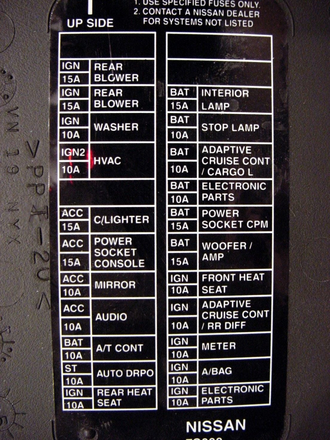
The fuse box diagram is organized in a logical manner, typically with a table or grid that lists each fuse and relay by its identifier (number or letter-number combination). The table then provides a brief description of the component or circuit that the fuse protects, along with its amperage rating. The diagram often includes a physical layout of the fuse box, showing the location of each fuse and relay. By cross-referencing the identifier on the fuse box with the corresponding entry in the table, you can quickly determine the function of any fuse or relay.
For example, if your radio stops working, you would first consult the fuse box diagram. You would look for an entry labeled "Radio" or "Audio System" and note the corresponding fuse number and amperage rating. You would then locate that fuse in the fuse box and inspect it. If the fuse is blown (the metal element inside is broken or blackened), you would replace it with a new fuse of the same amperage rating.
Real-World Use: Basic Troubleshooting Tips
Here are some basic troubleshooting tips using the fuse box diagram:
- Start with the obvious: If a component isn't working, check the corresponding fuse first. It's the simplest and most common cause of electrical problems.
- Visual Inspection: Before removing a fuse, visually inspect it for any signs of damage, such as a broken filament or blackened glass.
- Fuse Tester: A fuse tester is a simple tool that can quickly check the continuity of a fuse without removing it.
- Proper Replacement: Always replace a blown fuse with a fuse of the same amperage rating. Never use a fuse with a higher rating.
- Persistent Problems: If a fuse blows repeatedly, there is likely a short circuit or overload in the circuit. Further investigation is needed to identify and repair the underlying problem.
- Consult the Manual: Your vehicle's owner's manual may contain additional information about the fuse box diagram and electrical system.
Safety: Highlight Risky Components
Working with electrical systems can be dangerous. Here are some safety precautions to keep in mind:
- Disconnect the Battery: Before working on the electrical system, disconnect the negative terminal of the battery. This will prevent accidental short circuits and electric shocks.
- Avoid Water: Never work on the electrical system in wet conditions.
- Use Insulated Tools: Use tools with insulated handles to protect yourself from electric shock.
- High-Current Circuits: Be particularly careful when working with high-current circuits, such as the starter motor circuit or the alternator circuit. These circuits can deliver a powerful electric shock.
- Airbag Systems: The airbag system is a sensitive and potentially dangerous component. If you need to work near the airbag control module or wiring, disconnect the battery and wait at least 10 minutes to allow the system to discharge.
Disclaimer: This article provides general information about the 2004 Nissan Titan fuse box diagram. Specific details may vary depending on the trim level and options of your vehicle. Always consult the official factory service manual or a qualified technician for accurate and detailed information.
Remember to always prioritize safety when working on your vehicle's electrical system. If you're not comfortable performing electrical repairs, it's best to consult a qualified mechanic.
We have the 2004 Nissan Titan fuse box diagram available for download. Please feel free to download the diagram for your reference.