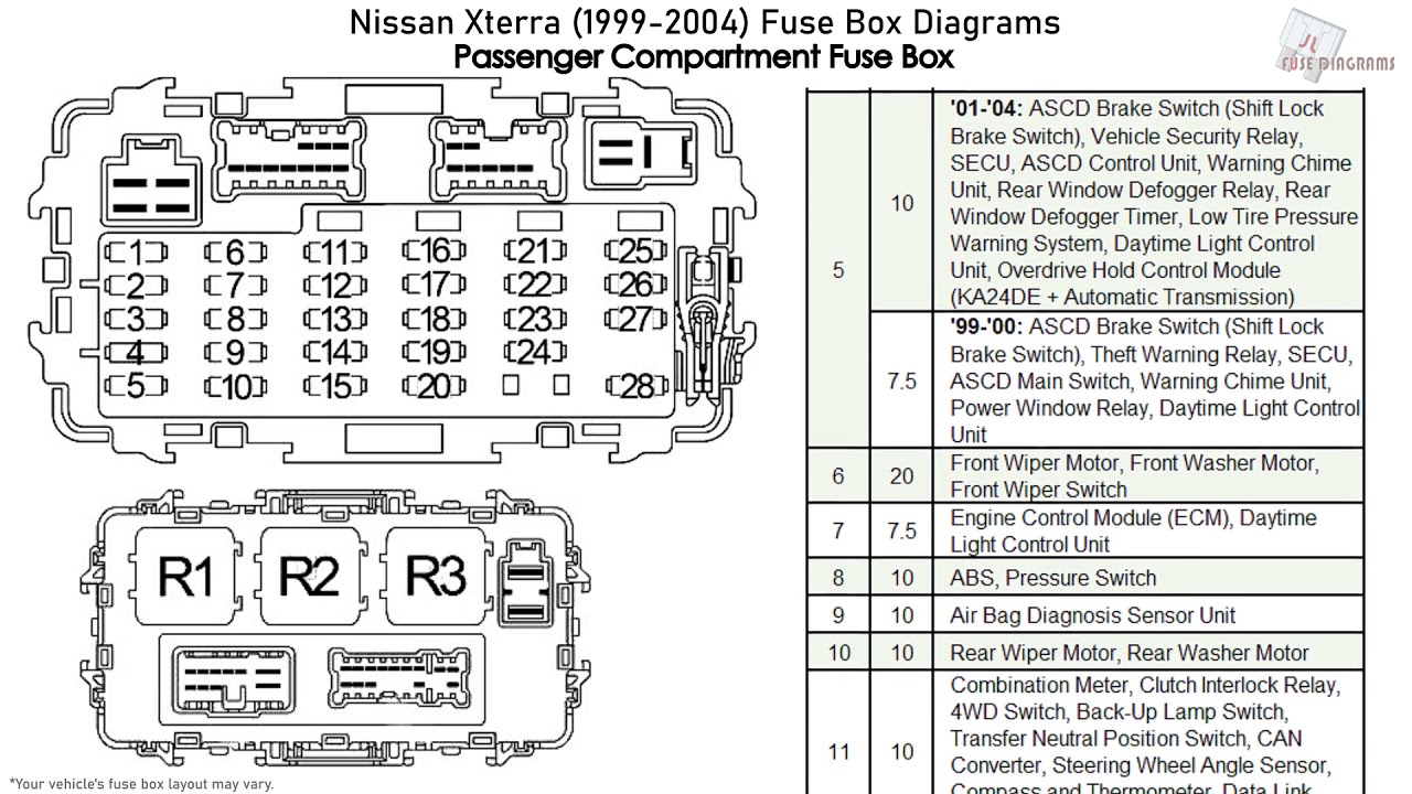
2004 Nissan Xterra Fuse Box Diagram
For the intermediate DIYer, having a solid grasp of your vehicle's electrical system is invaluable. It's the difference between a frustrating tow and a successful roadside repair. And when it comes to electrical troubleshooting, the fuse box diagram is your best friend. Specifically, we're focusing on the 2004 Nissan Xterra fuse box diagram in this article. This isn't just a pretty picture; it's a roadmap to your vehicle's electrical health.
Purpose of the Fuse Box Diagram
Why do you need this diagram? Several reasons, primarily:
- Electrical Repairs: A blown fuse is often the culprit behind a malfunctioning component. Identifying the correct fuse to replace is impossible without the diagram.
- Adding Accessories: Installing aftermarket accessories like lights or a new stereo requires tapping into the electrical system. Knowing which circuits can handle the additional load is crucial to prevent overloads and potential fires.
- Understanding Your Vehicle: Familiarizing yourself with the fuse box diagram gives you a deeper understanding of how your Xterra's electrical system is organized and protected.
- Troubleshooting: When diagnosing electrical issues, the diagram helps you trace circuits and identify potential problem areas.
- Safety: Understanding which fuses protect critical systems like the airbags and ABS allows for safe and informed troubleshooting.
Key Specs and Main Parts of the 2004 Xterra Fuse Boxes
The 2004 Nissan Xterra typically has two main fuse box locations:
Interior Fuse Box
Located inside the cabin, usually under the dashboard on the driver's side. This box typically houses fuses for components like:
- Interior lights
- Radio
- Power windows and locks
- Wipers
- Various control modules
Engine Compartment Fuse Box
Found under the hood, near the engine. This box contains fuses and relays for more critical components like:
- Headlights and taillights
- Fuel pump
- Ignition system
- Engine control unit (ECU)
- Anti-lock braking system (ABS)
- Air conditioning
Key Specs: The fuses are rated in amps (A), indicating the maximum current they can handle before blowing. Common ratings include 5A, 7.5A, 10A, 15A, 20A, 25A, and 30A. Always replace a blown fuse with one of the same amperage rating. Using a higher amperage fuse can overload the circuit and cause damage or fire.
Understanding the Symbols on the Fuse Box Diagram
Fuse box diagrams aren't just grids of squares; they use symbols to represent different components and circuit properties. Here's a breakdown of common symbols:
- Lines: Lines represent wires or electrical connections. Thicker lines usually indicate a higher current capacity.
- Colors: Wire colors are often indicated (e.g., BLU for blue, RED for red, GRN for green). These are crucial for tracing circuits.
- Fuse Symbol: Typically a small rectangle with a zigzag line running through it.
- Relay Symbol: A box with connecting lines, often including a coil symbol. Relays act as electrical switches, allowing a low-current circuit to control a high-current circuit.
- Component Symbols: Simplified icons representing the various components protected by the fuses, such as a lightbulb for headlights, a fan for the blower motor, etc. These vary by the diagram, but will typically be obvious.
Important note: Diagrams can vary slightly depending on the specific year and trim level of your Xterra. Always refer to the diagram that corresponds to your vehicle's VIN.
How the Fuse Box Works: Circuit Protection
The core principle is simple: overcurrent protection. Fuses are designed to be the weakest link in a circuit. If the current exceeds the fuse's rating, the fuse's internal filament melts (blows), breaking the circuit and preventing damage to the connected components. This prevents overheating, potential fires, and damage to expensive components.
Think of it like a dam on a river. The dam (fuse) is designed to hold a certain amount of water (current). If the water level (current) gets too high, the dam breaks, preventing the flood (overload) from reaching the town downstream (electrical components).
Relays, on the other hand, are remotely controlled switches. They're used to control high-current circuits with a low-current signal. For example, the headlights use a relay because the switch on the dashboard isn't designed to handle the high current needed to power the headlights directly. The dashboard switch activates the relay, which then closes the high-current circuit to the headlights.
Real-World Use: Basic Troubleshooting Tips
Here's how the fuse box diagram can save you time and money:
- Identify the Blown Fuse: Locate the diagram (usually in the owner's manual or on the fuse box cover itself). Find the fuse corresponding to the malfunctioning component (e.g., power windows). Visually inspect the fuse. A blown fuse will have a broken filament inside.
- Test the Fuse: If you can't visually confirm the fuse is blown, use a multimeter. Set the multimeter to continuity mode (usually indicated by a sound or symbol). Touch the probes to the two terminals on the fuse. If there's no continuity, the fuse is blown.
- Replace the Fuse: Replace the blown fuse with a new one of the same amperage rating.
- If the Fuse Blows Again: This indicates a short circuit or overload in the circuit. Don't just keep replacing the fuse with higher amperage fuses; this is extremely dangerous. Investigate the circuit to find the source of the problem. This may involve checking wiring for damage, looking for corroded connections, or testing the component itself.
- Using the Diagram for Accessory Installation: The diagram can show available circuits for tapping into for accessories. Always calculate the load of the accessory before tapping into a circuit, and ensure the circuit can handle the additional current. Use an add-a-circuit fuse tap for a clean and safe connection.
Example: Your radio suddenly stops working. Check the interior fuse box diagram. Locate the fuse labeled "Radio." If the fuse is blown, replace it. If it blows again immediately, there's a short circuit in the radio wiring or the radio itself is faulty.
Safety Precautions
Working with electrical systems can be dangerous. Here are some crucial safety precautions:
- Disconnect the Battery: Before working on any electrical circuits, disconnect the negative terminal of the battery. This prevents accidental shorts and electrical shocks.
- Work in a Well-Lit Area: Good visibility is essential for safe and accurate work.
- Use Insulated Tools: Use tools with insulated handles to prevent electrical shock.
- Never Replace a Fuse with a Higher Amperage: As stated before, this can cause serious damage or fire.
- Be Careful Around High-Current Components: Components like the alternator and starter motor carry high currents and can deliver a dangerous shock. Avoid touching these components while the engine is running or the battery is connected.
- Airbag System: Fuses related to the airbag system should be handled with extreme caution. Improper handling can cause the airbags to deploy accidentally. It's generally best to leave airbag system repairs to a qualified technician.
- Fuel System: Fuses and relays for the fuel pump can present a fire hazard if not handled correctly. Disconnect the battery and take proper precautions when working on these components.
Risky Components: Be extra cautious when dealing with fuses related to the airbag system (SRS), fuel pump, and ABS (Anti-lock Braking System). Incorrect handling of these systems can lead to serious injury or damage.
By understanding and utilizing the 2004 Nissan Xterra fuse box diagram, you can effectively diagnose and resolve electrical issues, saving time, money, and potential headaches. Remember to prioritize safety and always consult a qualified technician if you're unsure about any aspect of the repair.
We have the complete 2004 Nissan Xterra Fuse Box Diagram file ready for you. Contact us for downloading instruction.