2004 Toyota Camry Accelerator Pedal Position Sensor Diagram
Alright, let's dive into the Accelerator Pedal Position (APP) sensor diagram for the 2004 Toyota Camry. Whether you're troubleshooting a pesky check engine light, trying to understand your car's drive-by-wire system, or just expanding your automotive knowledge, understanding this diagram is crucial. We're going to break it down in a way that's clear, concise, and applicable to real-world scenarios.
Purpose of the APP Sensor and Diagram
The Accelerator Pedal Position (APP) sensor is a critical component in modern vehicles with electronic throttle control (ETC), often referred to as "drive-by-wire." Instead of a direct mechanical linkage between the accelerator pedal and the throttle body, the APP sensor translates your foot's position into an electrical signal. This signal is then sent to the Engine Control Unit (ECU), which interprets the signal and adjusts the throttle plate accordingly.
Why does the diagram matter? Well, without a diagram, diagnosing issues within the APP sensor circuit becomes a real guessing game. The diagram acts as a roadmap, showing you the wiring connections, sensor pinouts, and signal pathways. This helps with:
- Troubleshooting: Identifying shorts, opens, or incorrect voltage readings in the circuit.
- Component Testing: Determining if the sensor itself is functioning correctly.
- Wiring Repairs: Accurately repairing damaged or corroded wires.
- Understanding the System: Gaining a deeper understanding of how the ETC system operates.
Key Specs and Main Parts
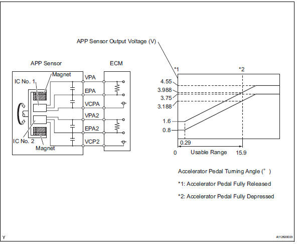
The 2004 Toyota Camry typically uses a dual APP sensor. This means there are two potentiometers housed within the sensor assembly. This redundancy is crucial for safety; if one sensor fails, the ECU can detect the discrepancy between the two signals and enter a limp-home mode, preventing uncontrolled acceleration.
Here’s a breakdown of the main parts and some typical specs:
- APP Sensor Assembly: The physical sensor mounted near the accelerator pedal.
- Potentiometers (POTs): Variable resistors within the sensor that change resistance based on pedal position. Usually two are installed for redundancy.
- Wiring Harness Connector: Connects the sensor to the vehicle's wiring harness. The 2004 Camry likely uses a connector with 5 or 6 pins.
- ECU (Engine Control Unit): The "brain" of the car that receives the APP sensor signals and controls the throttle.
- Voltage Supply: Typically a 5-volt reference voltage supplied by the ECU to the APP sensor.
- Ground: Provides a ground path for the sensor.
- Signal Wires: Carry the voltage signals from the sensor to the ECU. There will be two signal wires, one for each POT.
Typical Voltage Ranges: The APP sensor signal voltages typically range from around 0.5 volts at closed throttle to around 4.5 volts at wide-open throttle. These ranges can vary slightly depending on the specific sensor and calibration.
Understanding the Symbols
The APP sensor diagram isn't just a bunch of lines and boxes. Each element has a specific meaning. Let's decode some common symbols you'll find:
- Solid Lines: Represent wires carrying electrical signals.
- Dotted Lines: Might indicate shielded wires or ground connections.
- Rectangles: Typically represent components like the ECU or relays.
- Circles: Often denote connectors or splices in the wiring harness.
- Ground Symbol: A symbol that looks like an upside-down triangle or a series of horizontal lines decreasing in size, indicating a connection to ground.
- Resistor Symbol (Zig-zag line): Represents a resistor within the APP sensor, specifically the potentiometers.
- Voltage Source (Vcc or +5V): Indicates a voltage supply, usually 5 volts in this case.
- Pin Numbers: Numbers adjacent to connectors indicate the pin numbers for each wire.
- Wire Colors: Abbreviations like "BLU" for blue, "RED" for red, "GRN" for green, "BLK" for black, "WHT" for white, "YEL" for yellow. These are crucial for identifying the correct wires.
Pay close attention to the wire colors and pin numbers. These are essential for accurate diagnosis and repair. A mistake here can lead to further problems.
How It Works: From Pedal to Throttle
Here’s a simplified explanation of how the APP sensor system works:
- Pedal Press: You press the accelerator pedal.
- Resistance Change: This movement changes the resistance of the potentiometers inside the APP sensor.
- Voltage Signal: The varying resistance affects the voltage signal sent to the ECU. Each potentiometer sends a different voltage signal.
- ECU Interpretation: The ECU reads these voltage signals. The ECU has a programmed relationship between the two voltages. If the voltages don't match, the ECU detects an error.
- Throttle Control: Based on the APP sensor signals, the ECU controls the throttle plate actuator motor to open or close the throttle.
- Engine Response: The engine responds by increasing or decreasing power.
The ECU constantly monitors the APP sensor signals for plausibility. This means it checks if the signals are within expected ranges and if the two signals are correlated correctly. If the ECU detects an issue, it will likely trigger a Diagnostic Trouble Code (DTC) and illuminate the check engine light.
Real-World Use: Basic Troubleshooting Tips
Let's say you have a check engine light and suspect a problem with the APP sensor. Here are some basic troubleshooting steps:
- Scan for DTCs: Use an OBD-II scanner to retrieve the Diagnostic Trouble Codes (DTCs). Common codes related to the APP sensor include P0120-P0125 and P2135-P2138.
- Consult the Diagram: Locate the APP sensor diagram for your 2004 Camry (which we have available for download, by the way!).
- Visual Inspection: Check the APP sensor connector and wiring harness for any signs of damage, corrosion, or loose connections.
- Voltage Testing: Using a multimeter, check the voltage at the APP sensor connector with the ignition on. Verify that you have the correct voltage supply (typically 5V) and ground.
- Signal Testing: With the ignition on and the accelerator pedal at rest, measure the voltage on the signal wires. Slowly depress the accelerator pedal and observe the voltage change. The voltage should increase smoothly and proportionally to pedal position.
- Continuity Testing: With the ignition off, disconnect the APP sensor connector and check the continuity of the wiring from the sensor connector to the ECU connector. This will help identify any open circuits.
Important Note: Always disconnect the negative battery terminal before working on any electrical components to prevent accidental shorts.
Safety: Risky Components
While the APP sensor itself isn't inherently dangerous, working on the electrical system requires caution. The ECU can control things you might not expect, so safety is crucial.
- High Voltage: The ignition system operates at very high voltages. Avoid contact with ignition components when the engine is running.
- Fuel System: The fuel system is under pressure. Depressurize the fuel system before disconnecting any fuel lines.
- Airbag System: The airbag system is explosive. Disconnect the battery and wait at least 10 minutes before working near the airbag modules.
- ECU Damage: Incorrect wiring or voltage can damage the ECU. Always double-check your connections before applying power.
Disclaimer: This information is for educational purposes only and should not be considered a substitute for professional automotive advice. If you are not comfortable working on your car, consult a qualified mechanic.
We have the 2004 Toyota Camry Accelerator Pedal Position Sensor Diagram available for download to further assist you in your diagnostics and repairs. Access it now to gain a more in-depth understanding of your vehicle's system.