2004 Toyota Camry Throttle Assembly Diagram
The 2004 Toyota Camry, a vehicle renowned for its reliability, still benefits from occasional maintenance and repair. Understanding the throttle assembly is crucial for diagnosing and resolving engine performance issues. This article provides a detailed overview of the 2004 Camry's throttle assembly diagram, empowering you, the experienced DIYer, to tackle common problems with confidence. We'll break down the components, explain the system's operation, and offer troubleshooting tips.
Purpose of the Throttle Assembly Diagram
A throttle assembly diagram serves multiple essential purposes:
- Diagnosis: It provides a visual reference for identifying components when troubleshooting engine performance issues such as rough idling, stalling, or poor acceleration.
- Repair: The diagram guides you in disassembling and reassembling the throttle body during cleaning, replacement of parts like the throttle position sensor (TPS), or idle air control (IAC) valve.
- Learning: Studying the diagram helps you understand the relationship between various parts and how they contribute to overall engine operation. This is particularly valuable for those seeking to enhance their automotive knowledge.
- Modification: For those interested in performance modifications or upgrades, the diagram serves as a baseline for understanding the system's original configuration.
In essence, the diagram is your roadmap for navigating the intricacies of the throttle system. And great news, we have the actual file available to download for your convenience – just follow the link at the bottom of the article!
Key Specs and Main Parts
The 2004 Toyota Camry (specifically models with the 2.4L 2AZ-FE engine, the most common) uses an electronically controlled throttle, also known as a drive-by-wire system. This means there's no direct mechanical linkage between the accelerator pedal and the throttle plate. Instead, sensors and actuators work together to control airflow.
Main Components:
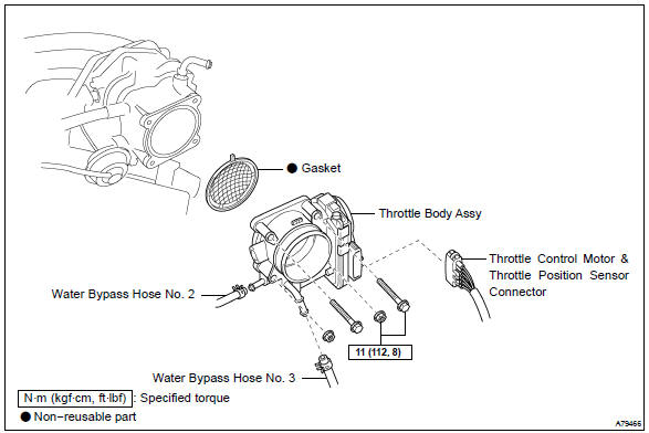
- Throttle Body: The central housing that contains the throttle plate and directs airflow into the intake manifold.
- Throttle Plate: A valve inside the throttle body that rotates to control the amount of air entering the engine. Its angle is regulated by the throttle control motor.
- Throttle Position Sensor (TPS): A potentiometer that measures the throttle plate's angle and sends a corresponding voltage signal to the Engine Control Unit (ECU). The TPS signal is crucial for determining fuel injection quantity and ignition timing.
- Throttle Control Motor: An electric motor that opens and closes the throttle plate based on signals from the ECU. It precisely controls airflow, offering a more responsive and efficient system compared to mechanical throttles.
- Accelerator Pedal Position Sensor (APPS): Located at the accelerator pedal, this sensor monitors the driver's input (how much they press the pedal) and transmits this information to the ECU. It's essentially the "brain" of the drive-by-wire system.
- Idle Air Control (IAC) Valve: Also referred to as the bypass air control valve, the IAC regulates engine idle speed by allowing a small amount of air to bypass the throttle plate when it's closed.
- Engine Control Unit (ECU): The "brain" of the engine management system. It receives signals from the TPS, APPS, and other sensors, and uses this information to control the throttle control motor, fuel injectors, and ignition system.
- Intake Air Temperature (IAT) Sensor: Measures the temperature of the air entering the intake manifold. This information is used by the ECU to adjust fuel mixture.
Diagram Symbols and Conventions
Throttle assembly diagrams, like all technical drawings, use standardized symbols and conventions to represent components and connections. Understanding these symbols is vital for interpreting the diagram correctly.
- Lines: Solid lines typically represent physical connections (e.g., wiring harnesses, vacuum lines). Dashed lines often indicate signal paths or communication lines within the electronic control system.
- Colors: Wiring diagrams frequently use color-coded wires to identify specific circuits. The diagram will usually include a key indicating the color of each wire and its function. For example, a red wire might indicate a power supply, while a black wire might indicate ground.
- Component Symbols: Each component has a specific symbol. For example, a resistor is usually represented by a zigzag line, a capacitor by two parallel lines, and a sensor by a box with an arrow pointing towards it. The legend on the diagram should identify all the symbols used.
- Connector Symbols: Connectors, where wires are joined together, are often shown as circles, squares, or rectangles with numbers indicating the pin numbers.
- Abbreviations: Pay attention to abbreviations. Common ones include TPS (Throttle Position Sensor), APPS (Accelerator Pedal Position Sensor), ECU (Engine Control Unit), and IAC (Idle Air Control).
How It Works
The 2004 Camry's electronic throttle system operates as follows:
- The driver presses the accelerator pedal, which changes the resistance value of the APPS.
- The APPS sends a signal to the ECU, indicating the desired level of acceleration.
- The ECU processes this signal, along with data from other sensors (TPS, IAT, engine speed, etc.).
- The ECU sends a command to the throttle control motor.
- The throttle control motor rotates the throttle plate to the appropriate angle.
- The TPS monitors the actual throttle plate angle and provides feedback to the ECU. This feedback loop ensures that the throttle plate is positioned accurately.
- The IAC valve regulates airflow during idle to maintain a stable engine speed, especially when the throttle plate is fully closed.
The entire process happens almost instantaneously, providing a smooth and responsive driving experience.
Real-World Use and Basic Troubleshooting
Let's consider some common problems and how the throttle assembly diagram can assist in troubleshooting:
- Rough Idling: The IAC valve might be dirty or malfunctioning. The diagram can help you locate the IAC valve for cleaning or replacement. Check the wiring connections to the IAC valve using the diagram as a guide.
- Poor Acceleration: The TPS might be faulty or sending incorrect signals to the ECU. Use a multimeter to test the TPS output voltage according to the specifications outlined in the repair manual (which the diagram supplements). Compare the readings to the expected values.
- Check Engine Light (CEL) with Throttle-Related Codes: Scan the ECU for diagnostic trouble codes (DTCs). Codes such as P0120 (TPS Circuit Malfunction) or P1120 (Accelerator Pedal Position Sensor Circuit Range/Performance) point directly to the throttle system. The diagram will help you trace the circuit related to the faulty sensor.
- Stalling: A faulty throttle control motor or a blockage in the throttle body can cause stalling. The diagram can help you identify the throttle control motor and trace its wiring. Visually inspect the throttle body for carbon buildup and clean it as needed.
Example: If you suspect a faulty TPS, the diagram shows you where the TPS is located on the throttle body, the color coding of the wires connected to it, and the pin numbers. This information is essential for performing voltage tests and verifying its functionality.
Safety Precautions
Working on the throttle assembly requires caution. Here are some safety tips:
- Disconnect the Battery: Always disconnect the negative battery terminal before working on any electrical components. This prevents accidental shorts and potential damage to the ECU.
- Handle Sensors Carefully: Sensors like the TPS and APPS are sensitive electronic devices. Avoid dropping them or exposing them to static electricity.
- Avoid Cleaning with Harsh Chemicals: Use throttle body cleaner specifically designed for automotive use. Avoid using harsh solvents that can damage the sensors or seals.
- Be extremely careful around the throttle plate itself. Never force the throttle plate open manually, especially on a drive-by-wire system. Doing so can damage the throttle control motor or other components.
- Hot Components: The engine, particularly the exhaust manifold and surrounding areas, can be extremely hot. Allow the engine to cool down completely before working on the throttle assembly.
Remember that the throttle system directly impacts engine performance and safety. If you're not comfortable performing these tasks, consult a qualified mechanic.
We've covered the essential aspects of the 2004 Toyota Camry throttle assembly diagram. Remember to always consult the factory service manual for specific procedures and torque specifications. Now that you have a solid understanding of the components, operation, and troubleshooting techniques, you're better equipped to tackle throttle-related issues on your Camry.
And as promised, you can download the 2004 Toyota Camry Throttle Assembly Diagram here.