2004 Toyota Highlander Rear Suspension Diagram
Understanding the rear suspension of your 2004 Toyota Highlander is crucial for maintaining a smooth ride, ensuring vehicle safety, and potentially saving money on repairs. This article breaks down the rear suspension diagram, explaining its components, functionality, and how to use it for troubleshooting. Think of this as your expert guide to understanding the complexities of your Highlander's rear end.
Purpose of Understanding the Diagram
Why bother digging into a rear suspension diagram? Several reasons:
- Repair and Maintenance: The diagram helps you identify specific parts for replacement or repair. No more guessing at names – you'll know exactly what you need.
- Troubleshooting: By visually tracing the system, you can pinpoint potential problem areas based on symptoms like excessive bouncing, unusual noises, or uneven tire wear.
- Modification: Planning to lift or lower your Highlander? The diagram helps you understand the geometry and potential impacts of modifications.
- Learning: Simply put, understanding how your car works is empowering. It gives you more control over its upkeep and allows you to make informed decisions.
Key Specs and Main Parts
The 2004 Toyota Highlander utilizes a double-wishbone rear suspension system. This design is known for its excellent handling characteristics and ability to maintain consistent tire contact with the road. Here's a breakdown of the key components:
- Upper and Lower Control Arms: These are the primary structural members connecting the wheel hub to the vehicle's frame. They control the wheel's vertical movement and limit lateral movement. They pivot on bushings, which are rubber or polyurethane components that absorb vibrations and allow for controlled movement.
- Coil Springs: Located around the shock absorbers, these springs provide the primary support for the vehicle's weight and absorb bumps in the road. The spring rate determines how stiff the suspension is.
- Shock Absorbers (Dampers): These control the oscillation of the springs, preventing excessive bouncing. They work by forcing fluid through small orifices, converting kinetic energy into heat. There are different types of shocks, including gas-charged and hydraulic.
- Wheel Hub/Bearing Assembly: This assembly houses the wheel bearing, which allows the wheel to rotate smoothly. It's bolted to the control arms and connects to the axle.
- Trailing Arm/Knuckle (depending on variation): Some variations may have a trailing arm configuration integrated into the knuckle design. This adds additional stability and helps control wheel alignment.
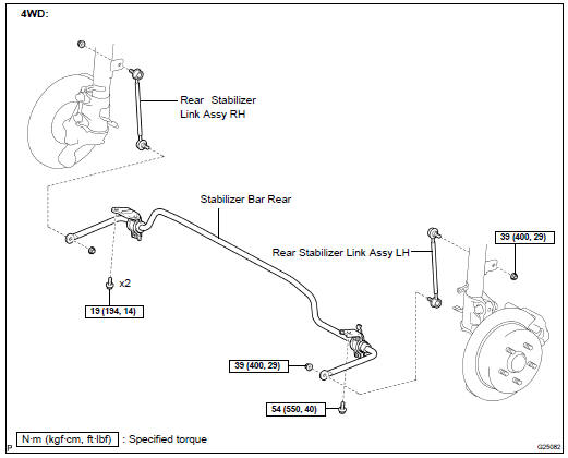
- Stabilizer Bar (Sway Bar): This bar connects the left and right sides of the suspension, reducing body roll during cornering. It twists when one wheel moves up or down more than the other, transferring some of the force to the opposite wheel. It's connected to the suspension with end links.
- Brake Components: While not strictly suspension, the rear brakes are closely integrated. The diagram shows the calipers, rotors, and brake lines.
- Subframe (Rear Crossmember): This is a structural component that supports the suspension components and attaches them to the vehicle's chassis.
Understanding Symbols in the Diagram
The diagram uses standard automotive symbols to represent various components and connections. Learning these symbols makes the diagram much easier to read:
- Solid Lines: Generally represent physical components, such as control arms, springs, and shock absorbers. Thicker lines often indicate larger or more structural components.
- Dashed Lines: May indicate hidden components or connections that are behind other parts. They can also represent fluid lines, such as brake lines.
- Circles/Dots: Usually represent pivot points or joints, such as where the control arms connect to the frame or wheel hub.
- Arrows: Indicate direction of movement or force. For example, an arrow on a shock absorber might indicate the direction of damping force.
- Color Coding: In some diagrams, different colors might be used to distinguish between different types of components or systems. Consult the diagram's legend for specific color meanings. Commonly, brake lines are a different color.
- Component Labels: Each part will have a corresponding label, typically a number or abbreviation, that you can cross-reference with a parts list or legend.
How the Rear Suspension Works
The double-wishbone suspension works by allowing the wheels to move up and down independently, while maintaining a relatively constant camber angle (the angle of the wheel relative to the vertical axis). When the wheel encounters a bump:
- The wheel moves upward, compressing the coil spring.
- The shock absorber dampens the spring's oscillation, preventing excessive bouncing.
- The control arms guide the wheel's movement, keeping it relatively perpendicular to the road.
- The stabilizer bar resists body roll during cornering by transferring force between the wheels.
This coordinated movement provides a comfortable ride, predictable handling, and good tire contact with the road.
Real-World Use: Basic Troubleshooting
Here are some basic troubleshooting tips using the rear suspension diagram:
- Symptom: Excessive Bouncing: Check the shock absorbers for leaks or damage. If they're leaking fluid, they need to be replaced. Use the diagram to identify the shock absorber and its mounting points.
- Symptom: Clunking Noises: Inspect the bushings in the control arms and stabilizer bar end links. Worn or damaged bushings can cause clunking noises. The diagram will show the location of all bushings.
- Symptom: Uneven Tire Wear: This could be caused by misaligned suspension components. Have the alignment checked by a professional. The diagram can help you understand which components affect alignment angles (camber, toe, caster – though caster is not adjustable on the rear).
- Symptom: Squeaking Noises: Often caused by dry or worn bushings. You can try lubricating the bushings (if accessible), but replacement is often the best solution.
When inspecting, pay close attention to any signs of damage, such as cracks, bends, or corrosion. Use the diagram to ensure all components are properly installed and torqued to the correct specifications.
Safety Considerations
Working on suspension components can be dangerous due to the high spring forces involved. Never attempt to disassemble a suspension component without using proper spring compressors. Spring compressors safely compress the coil spring, allowing you to remove the shock absorber and other components without the risk of the spring suddenly releasing and causing serious injury. Always use jack stands to support the vehicle before working underneath it. Never rely solely on a jack. Brake lines are also a potential hazard – avoid kinking or damaging them. If you're not comfortable working on suspension components, it's best to leave the job to a qualified mechanic.
Ready to Dive Deeper?
You now have a solid understanding of the 2004 Toyota Highlander's rear suspension. For a more detailed look, we have the complete rear suspension diagram available for download. This detailed resource will provide you with specific part numbers, torque specifications, and exploded views to aid in your repairs and maintenance.