2005 Chevrolet Malibu Engine Diagram
Alright, let's dive into the engine diagram of a 2005 Chevrolet Malibu. Whether you're planning some serious repairs, want to deepen your understanding of how your car ticks, or even contemplating some performance mods, a solid grasp of the engine layout is crucial. This isn't just a pretty picture; it's your roadmap to understanding the heart of your Malibu.
Purpose of the Engine Diagram
Why bother with this diagram? Simple. It serves as your visual guide for:
- Troubleshooting: Pinpointing the source of a problem, whether it's a misfire, a leak, or a strange noise.
- Maintenance & Repair: Locating components for replacement, inspection, or cleaning.
- Understanding System Interconnections: Seeing how the different parts work together (fuel, ignition, cooling, etc.).
- Modifications: Planning and executing performance upgrades.
- General Education: Just learning more about your car!
Without it, you're essentially working blind, relying on guesswork which can lead to costly mistakes and further damage.
Key Specs and Main Parts
The 2005 Malibu typically came with a couple of engine options. The most common were:
- 2.2L Ecotec L61 Inline-4: This is a 16-valve engine, known for its decent fuel economy and reasonable power. Its displacement is 2.2 liters.
- 3.5L LX9 V6: Offering more power, this is a 12-valve engine, with a larger displacement of 3.5 liters.
The engine diagram will visually represent all major components, but here are some of the key ones you'll regularly encounter:
- Cylinder Head: Houses the valves, camshaft(s), and spark plugs.
- Engine Block: The main structure containing the cylinders.
- Intake Manifold: Distributes air to the cylinders.
- Exhaust Manifold: Collects exhaust gases from the cylinders.
- Throttle Body: Controls the amount of air entering the engine.
- Fuel Injectors: Spray fuel into the intake manifold or directly into the cylinders (depending on the engine type).
- Fuel Rail: Supplies fuel to the injectors.
- Spark Plugs: Ignite the air-fuel mixture.
- Distributor/Ignition Coils: Provide the high voltage needed for the spark plugs (the 2.2L engine uses coil-on-plug ignition).
- Water Pump: Circulates coolant to regulate engine temperature.
- Thermostat: Controls the flow of coolant to the radiator.
- Radiator: Dissipates heat from the coolant.
- Alternator: Generates electricity to power the car's electrical system.
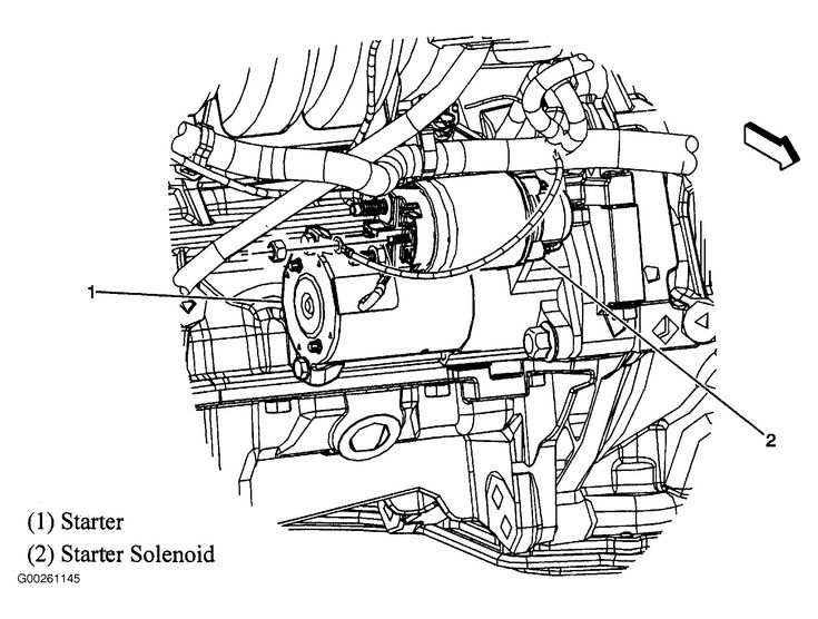
- Starter Motor: Cranks the engine to start it.
- Sensors: Such as the crankshaft position sensor (CKP), camshaft position sensor (CMP), mass airflow sensor (MAF), oxygen sensors (O2 sensors), and coolant temperature sensor (ECT). These provide data to the engine control module (ECM).
- Engine Control Module (ECM): The "brain" of the engine, which controls fuel injection, ignition timing, and other parameters.
Understanding the Symbols
Engine diagrams aren't just pictures; they use specific symbols to represent components and connections. Here's a breakdown:
- Solid Lines: Typically represent fluid lines (fuel, coolant, oil) or vacuum lines. The thickness can sometimes indicate the size or pressure of the line.
- Dashed Lines: Often used for electrical wiring or vacuum lines with lower pressure.
- Different Colors: Colors often denote the type of fluid or the function of a wire. For example:
- Red: Usually associated with positive battery voltage.
- Black: Typically represents ground.
- Blue/Green: Might indicate sensor signals.
- Component Symbols: Each component has a specific symbol. For example, a resistor might be a zigzag line, a capacitor might be two parallel lines, and a sensor will have its own unique icon. Again, consult the diagram's legend.
- Arrows: Indicate the direction of flow of fluids or electrical current.
How It Works (Simplified)
The engine diagram helps you visualize how all these components work together. In a nutshell:
- Air enters the engine through the intake system, regulated by the throttle body.
- Fuel is injected into the intake manifold or directly into the cylinders.
- The air-fuel mixture is compressed in the cylinders.
- The spark plugs ignite the mixture, causing combustion.
- The expanding gases push the pistons down, turning the crankshaft.
- The crankshaft rotates the wheels, propelling the car.
- Exhaust gases are expelled through the exhaust system.
- The ECM monitors various sensors to optimize fuel injection, ignition timing, and other parameters for efficient and powerful operation.
The diagram will show how these systems are interconnected – how the fuel system relies on the electrical system, how the cooling system maintains the engine temperature, and so on.
Real-World Use: Basic Troubleshooting Tips
Let's say your 2005 Malibu is experiencing a rough idle. Using the engine diagram, you can:
- Locate the vacuum lines: Check for any cracked or disconnected lines, which could cause a vacuum leak and a rough idle.
- Identify the MAF sensor: Inspect it for dirt or damage. A faulty MAF sensor can cause incorrect air-fuel mixture readings.
- Find the fuel injectors: Check the wiring connectors for corrosion or loose connections.
- Trace the spark plug wires or ignition coils: Ensure they are properly connected and in good condition.
The diagram gives you a starting point. From there, you can use a multimeter or other diagnostic tools to further pinpoint the problem.
Safety Considerations
Working on your car can be dangerous if you're not careful. Here are some crucial safety tips:
- Disconnect the Battery: Always disconnect the negative battery terminal before working on any electrical components.
- Fuel System: Gasoline is highly flammable. Never smoke or work near open flames when dealing with the fuel system. Relieve fuel pressure before disconnecting fuel lines.
- Cooling System: Coolant can be extremely hot, especially right after the engine has been running. Allow the engine to cool down completely before opening the radiator cap or working on the cooling system.
- High Voltage: Be extremely careful when working with the ignition system. High voltage can be lethal.
- Proper Tools: Use the right tools for the job. Using the wrong tool can damage components or cause injury.
Never work under a vehicle supported only by a jack. Use jack stands.
Conclusion
The 2005 Chevrolet Malibu engine diagram is an invaluable tool for any DIY mechanic or car enthusiast. By understanding the components, symbols, and system interconnections, you can effectively troubleshoot problems, perform maintenance, and even plan modifications. Remember to prioritize safety and consult the diagram's legend for accurate information.
We have the diagram available for download, simply click the download link below.