2005 Chevrolet Silverado Radio Wiring Harness
Let's dive into the radio wiring harness of a 2005 Chevrolet Silverado. Whether you're upgrading your head unit, troubleshooting a faulty sound system, or simply learning more about your truck's electrical architecture, understanding this harness is crucial. This article will break down the key components, wiring conventions, and practical applications, empowering you to confidently tackle radio-related projects on your Silverado.
Purpose of Understanding the 2005 Silverado Radio Wiring Harness
Why bother understanding this harness? Several reasons come to mind. First, repairs. A blown fuse, a corroded connector, or a damaged wire can all lead to radio malfunctions. Knowing the wiring allows you to pinpoint the source of the problem. Second, upgrades. Swapping out the factory head unit for a modern aftermarket system is a popular modification. Correctly identifying each wire is essential to ensure proper functionality and prevent electrical damage. Third, learning. Even if you don't have immediate plans to modify your radio, understanding its wiring can deepen your overall knowledge of automotive electrical systems. Finally, you may want to add an amplifier or additional speakers to your system. Tapping into the correct wires is key to successful upgrades.
Key Specs and Main Parts of the Harness
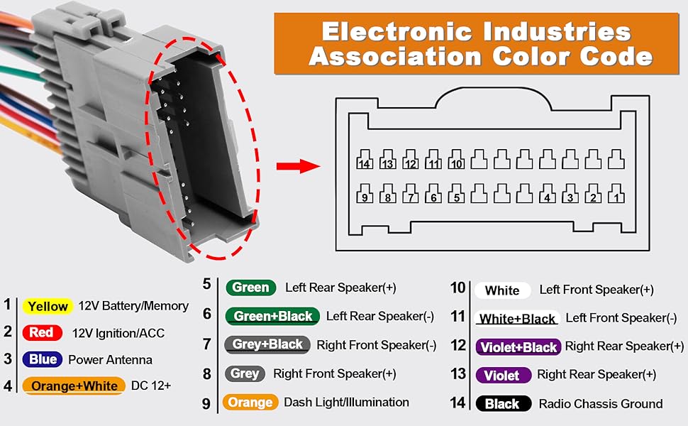
The 2005 Silverado radio wiring harness is a collection of wires, connectors, and terminals designed to interface the radio (or head unit) with the vehicle's electrical system. Here are the main parts:
- Power Wires: These provide the necessary voltage for the radio to operate. You'll typically find a constant 12V (battery) wire for memory retention and an ignition-switched 12V wire for powering the radio on and off with the key.
- Ground Wire: This provides a return path for the electrical current and is essential for completing the circuit.
- Speaker Wires: These carry the audio signal from the radio to the speakers. There are typically four pairs of speaker wires – one pair for each of the four speakers (front left, front right, rear left, rear right). Each speaker wire has a positive (+) and a negative (-) lead.
- Antenna Wire: This connects the radio to the antenna, allowing it to receive radio signals.
- Data Wires: Some radios have data wires for features like steering wheel controls, OnStar integration, or communication with the vehicle's computer (ECU/PCM). These wires often communicate using a protocol called CAN-BUS (Controller Area Network).
The harness connects to the back of the radio and often has a corresponding connector that plugs into the factory wiring in the dashboard. Aftermarket radios typically require an adapter harness to bridge the gap between the radio's connector and the factory wiring.
Understanding the Symbols in the Wiring Diagram
Wiring diagrams use standardized symbols to represent different components and connections. Here’s a breakdown of common symbols you'll encounter in a 2005 Silverado radio wiring diagram:
- Solid Lines: Represent wires. The thickness of the line doesn't necessarily indicate wire gauge, but often heavier lines might mean wires with more current capacity.
- Dashed Lines: Often represent shielded wires, ground connections, or wires that are not part of the core radio function (e.g., optional accessories).
- Circles: Can represent connectors, fuses, or other components.
- Squares: Can also represent components, or sometimes just a termination point for a wire.
- Arrowheads: Indicate the direction of current flow (though diagrams often omit these).
- Color Codes: Wires are typically identified by color codes (e.g., RED, BLU, GRN, YEL). These are crucial for identifying the correct wires in the harness. Consult the color code legend in the diagram.
Diagrams often use abbreviations to indicate the wire gauge, type, and function (e.g., "18GA RED/WHT" means an 18-gauge red wire with a white stripe). Understanding these abbreviations is essential for accurate identification.
How It Works: The Radio Wiring in Action
The radio wiring harness is a conduit for power, audio signals, and data. The constant 12V wire keeps the radio's memory alive, storing settings like preset stations and equalizer configurations. The ignition-switched 12V wire tells the radio when to turn on and off with the vehicle. The ground wire provides a stable reference point for the electrical system. The speaker wires carry the amplified audio signal to the speakers, where it is converted into sound waves. The antenna wire receives radio signals from the antenna. Data wires facilitate communication with other vehicle systems, allowing for features like steering wheel controls and OnStar integration.
When you turn on the ignition, the ignition-switched 12V wire provides power to the radio. The radio then draws power from the constant 12V wire to maintain its settings. The antenna receives radio signals, which are processed by the radio. The radio amplifies the audio signal and sends it to the speakers through the speaker wires. Any commands sent through steering wheel controls are communicated to the radio through the data wires.
Real-World Use: Basic Troubleshooting Tips
Here are some common radio-related problems and how the wiring diagram can help:
- No Power: Check the fuses related to the radio. Use a multimeter to test for voltage at the constant 12V and ignition-switched 12V wires at the radio connector. If there's no voltage, trace the wires back to the fuse box or battery to identify the break.
- No Sound: Ensure the radio is turned on and the volume is up. Check the speaker wires for continuity using a multimeter. If a speaker wire is open, trace it back to the speaker or the radio to find the break. Also verify the speaker is not blown.
- Poor Reception: Check the antenna connection at the back of the radio and at the base of the antenna. Make sure the antenna mast is intact.
- Steering Wheel Controls Not Working: Check the data wires for continuity and proper connection. Consult the wiring diagram to ensure the data wires are connected to the correct pins on the radio and the vehicle's computer. You might need a specific adapter that handles CAN-BUS integration.
Before performing any electrical work, disconnect the negative battery terminal to prevent short circuits and electrical damage. Always use a multimeter to verify voltage and continuity before making any connections.
Safety: Highlighting Risky Components
Working with automotive electrical systems can be dangerous if proper precautions are not taken. Here are some risky components to be aware of:
- Power Wires: These wires carry significant current and can cause electrical shock or burns if shorted to ground. Always disconnect the battery before working on these wires.
- Capacitors: Some radios contain capacitors that can store electrical charge even after the power is disconnected. Discharging these capacitors before working on the radio's internal circuitry is important. However, for the purposes of working with the wiring harness, this is less of a concern.
- Airbag Wiring: The radio harness may be routed near airbag wiring. Avoid disturbing or damaging airbag wiring, as this could cause accidental deployment of the airbags.
Always use insulated tools and wear safety glasses when working with electrical components. If you're not comfortable working with electrical systems, consult a qualified automotive electrician.
Remember, a thorough understanding of the 2005 Chevrolet Silverado radio wiring harness is invaluable for successful repairs, upgrades, and learning about your vehicle's electrical system. By familiarizing yourself with the components, symbols, and troubleshooting techniques described in this article, you'll be well-equipped to tackle radio-related projects with confidence.
We have the full 2005 Chevrolet Silverado radio wiring diagram file available for download. This diagram provides a comprehensive overview of the wiring harness, including wire colors, pin locations, and circuit diagrams. It's an invaluable resource for any serious DIYer.