2005 Chevrolet Trailblazer Fuse Box Diagram
Welcome, fellow gearheads! Today, we’re diving deep into the heart of the 2005 Chevrolet Trailblazer – specifically, its fuse box diagram. This seemingly simple piece of paper (or digital file, in our case) is an invaluable tool for anyone who wants to understand, maintain, or modify their Trailblazer. Knowing how to read and understand this diagram can save you time, money, and a whole lot of frustration when dealing with electrical issues.
Purpose: Why Master the Fuse Box Diagram?
Why should you, a seasoned DIYer, care about a fuse box diagram? There are several compelling reasons:
- Troubleshooting Electrical Problems: This is the most common use. If your headlights aren't working, your radio is dead, or your power windows refuse to budge, the fuse box is the first place to look. The diagram tells you which fuse protects which circuit.
- Performing Repairs: Need to replace a faulty sensor, relay, or other electrical component? The diagram helps you identify the correct fuse to disconnect before starting work, preventing accidental shorts and potential damage.
- Adding Accessories: Installing aftermarket accessories like amplifiers, lights, or remote starters requires tapping into the electrical system. The diagram allows you to find appropriate power sources and properly fuse your new circuits.
- Understanding Your Vehicle: For those who enjoy knowing how their car works, the fuse box diagram is a window into the electrical architecture of the Trailblazer.
Key Specs and Main Parts: A Tour of the Fuse Box
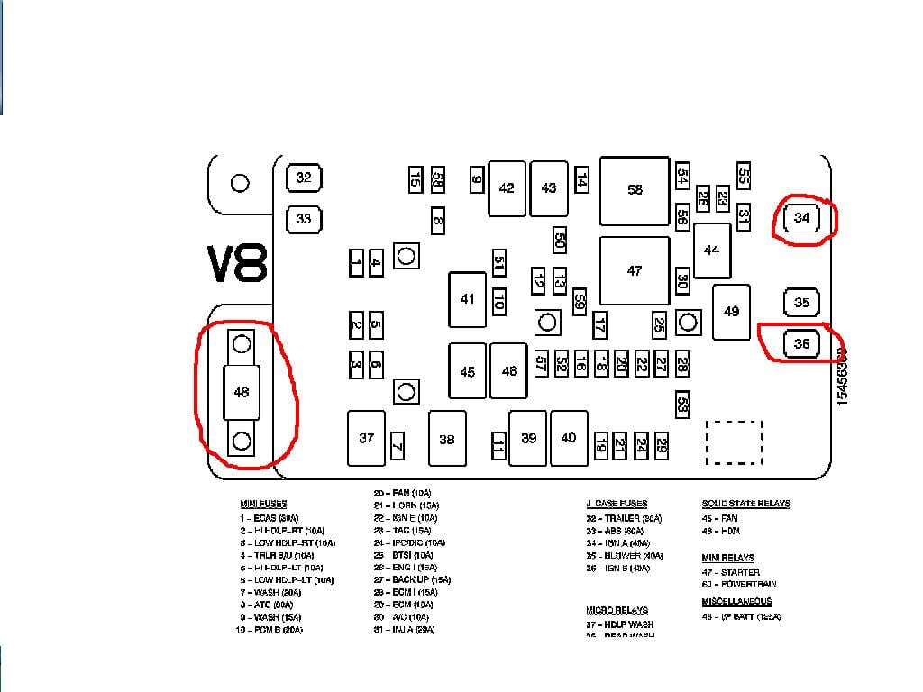
The 2005 Trailblazer typically has two fuse box locations: one under the hood (the underhood electrical center or UEC) and another inside the cabin, usually on the driver's side, often located on the side of the dashboard or under the instrument panel. Let’s look at each:
Underhood Electrical Center (UEC)
The UEC is the main distribution point for the vehicle's electrical power. It houses fuses and relays that control critical systems like the engine, transmission, headlights, cooling fan, and antilock braking system (ABS).
- Fuses: These are sacrificial devices designed to protect circuits from overcurrent. They come in various amperage ratings (e.g., 10A, 15A, 20A, 30A) and physical sizes (e.g., ATO, mini, maxi). The diagram specifies the correct amperage for each fuse.
- Relays: These are electrically operated switches that control high-current circuits. A small control signal from the vehicle's computer or a switch activates the relay, which then allows current to flow through the larger circuit. Common relays include the starter relay, fuel pump relay, and headlight relay.
- Circuit Breakers: Similar to fuses, but resettable. They interrupt the circuit in case of overcurrent, but can be manually reset or will automatically reset after a cooling period.
Interior Fuse Box
The interior fuse box typically handles circuits for accessories and interior components like the radio, power windows, power locks, climate control, and interior lighting.
- Fuses: Similar to the underhood fuses, these protect the circuits of the interior components.
- Relays: May also contain relays, often for accessories or specific interior functions.
Decoding the Symbols: The Language of the Diagram
The fuse box diagram isn't just a random assortment of squares and lines. It uses specific symbols and conventions to convey information. Let's break down the common elements:
- Fuses: Typically represented by a rectangle with a zigzag line inside. The amperage rating is usually printed next to the symbol.
- Relays: Often depicted as a square or rectangle with internal symbols representing the coil and contacts of the relay.
- Circuit Breakers: May be represented by a symbol similar to a fuse, but with a curved line or arrow indicating the reset function.
- Lines: Solid lines indicate electrical connections, while dashed lines may represent ground connections or control signals.
- Colors: Some diagrams use color-coding to differentiate between circuits or functions. For example, red might indicate a constant power source, while blue might represent a switched power source.
- Icons: The diagram often uses small icons to represent the function of each fuse or relay. These icons can depict headlights, a radio, a window, or other components. Look for a legend on the diagram that explains what each icon represents.
- Fuse/Relay Numbers: Each fuse and relay is assigned a unique number, which corresponds to its position in the fuse box. This numbering system helps you quickly locate the correct component.
How It Works: A System in Action
The fuse box is the central distribution point for electrical power in your Trailblazer. The battery provides the initial power source, which is then distributed through the fuse boxes to various components. Each circuit is protected by a fuse or circuit breaker, which acts as a safety valve. If a circuit experiences an overcurrent condition (e.g., a short circuit), the fuse will blow (melt) or the circuit breaker will trip, interrupting the flow of electricity and preventing damage to the wiring and components.
Relays act as intermediaries, allowing low-current signals to control high-current circuits. For example, when you turn on your headlights, a small current flows from the headlight switch to the headlight relay. This activates the relay, which then allows a much larger current to flow from the battery to the headlights.
Real-World Use: Basic Troubleshooting Tips
Here's a basic troubleshooting scenario:
- Symptom: Your radio doesn't turn on.
- Step 1: Consult the Diagram: Locate the fuse box diagram for your 2005 Trailblazer (remember, we have that file available!). Identify the fuse labeled for the radio.
- Step 2: Locate the Fuse: Find the corresponding fuse in the fuse box. The diagram will tell you the fuse number and location.
- Step 3: Inspect the Fuse: Visually inspect the fuse. If the thin wire inside the fuse is broken or blackened, the fuse is blown.
- Step 4: Replace the Fuse: Replace the blown fuse with a new fuse of the same amperage rating. Important: Always use the correct amperage. Using a higher amperage fuse can overload the circuit and cause a fire.
- Step 5: Test: Turn on the radio to see if it works. If the fuse blows again immediately, there's likely a short circuit in the radio wiring or the radio itself. Further diagnostics are required.
Important Note: If a fuse repeatedly blows, don't just keep replacing it with a higher amperage fuse! This is a recipe for disaster. A blown fuse indicates a problem in the circuit that needs to be addressed.
Safety: Respecting the Electrical System
Working with automotive electrical systems can be dangerous if you're not careful. Here are some safety precautions:
- Disconnect the Battery: Before working on any electrical component, disconnect the negative (-) terminal of the battery. This will prevent accidental shorts and electrical shocks.
- Avoid Water: Never work on electrical systems in wet conditions. Water is a conductor of electricity and can create a dangerous situation.
- Use Proper Tools: Use insulated tools designed for automotive electrical work.
- Identify High-Risk Components: Be particularly cautious when working around high-current components like the starter motor, alternator, and battery. These components can deliver a powerful electrical shock.
- Read the Diagram Carefully: Always refer to the fuse box diagram before working on any electrical circuit. This will help you identify the correct fuses and relays and avoid accidentally damaging other components.
Remember, the airbag system is a high-risk area. Improper handling can cause the airbags to deploy, resulting in serious injury. If you need to work on or around the airbag system, consult a qualified technician.
By understanding the fuse box diagram and following proper safety procedures, you can confidently diagnose and repair electrical problems on your 2005 Chevrolet Trailblazer. And remember, we have the complete 2005 Chevrolet Trailblazer fuse box diagram file available for you. Happy wrenching!