2005 Chevy Impala 3.4 Engine Diagram
So, you're diving into the 2005 Chevy Impala with the 3.4L LA1 V6 engine, huh? Excellent choice. It's a robust powerplant, but like any engine, understanding its inner workings is key to keeping it running smoothly, diagnosing issues effectively, and even performing some well-considered modifications. That's where a good engine diagram comes in. We're going to break down the 2005 Impala 3.4L engine diagram, focusing on the major components and what those squiggly lines and strange symbols actually mean.
Purpose: Why You Need This Diagram
Let's be honest, staring under the hood of a modern engine can feel like looking at an alien spaceship. The engine diagram acts as a roadmap. It’s invaluable for:
- Troubleshooting: Tracing vacuum lines, identifying sensors, and locating specific components quickly.
- Repair Work: Knowing the exact layout for replacing parts like spark plugs, fuel injectors, or the thermostat.
- Performance Upgrades: Planning modifications like cold air intakes, exhaust systems, or even a complete engine swap requires a solid understanding of the existing system.
- General Maintenance: Identifying maintenance points, such as oil filter location, coolant drain plugs, and bleed valves.
- Learning: Simply understanding how your engine works! It empowers you to make informed decisions about its care.
Think of it as the instruction manual that Chevy should have included, but didn't. Fortunately, we've got you covered.
Key Specs and Main Parts of the 3.4L LA1 V6
Before we dive into the diagram itself, let's quickly recap the key specifications and the main players:
- Engine Type: 3.4L LA1 V6 (also known as the GM 3400)
- Displacement: 3350 cc (204 cu in)
- Bore x Stroke: 92 mm x 84 mm (3.62 in x 3.31 in)
- Compression Ratio: 9.5:1
- Horsepower: Approximately 180-200 hp (depending on the exact model year)
- Torque: Approximately 205 lb-ft
- Fuel System: Sequential Fuel Injection (SFI)
- Ignition System: Distributorless Ignition System (DIS)
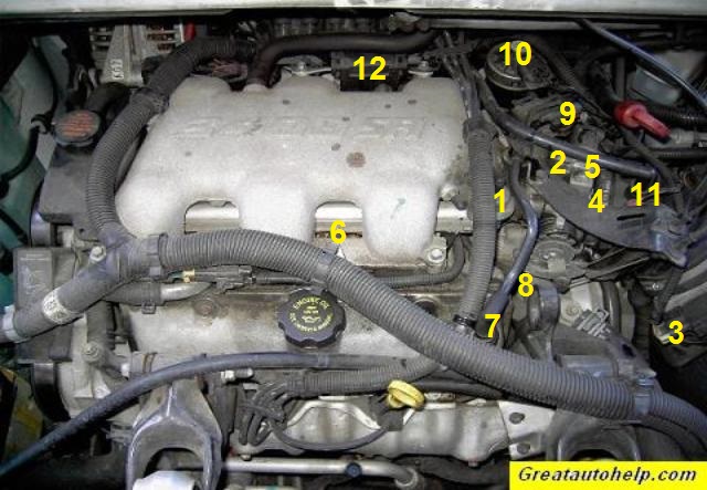
Now, for the major components you'll see in the diagram:
- Cylinder Head: Houses the valves, camshaft, and spark plugs. There are two, one for each bank of cylinders.
- Cylinder Block: The main structure of the engine, containing the cylinders themselves.
- Pistons: Move up and down within the cylinders, compressing the air/fuel mixture.
- Connecting Rods: Connect the pistons to the crankshaft.
- Crankshaft: Converts the reciprocating motion of the pistons into rotational motion.
- Camshaft: Controls the opening and closing of the intake and exhaust valves.
- Intake Manifold: Distributes the air/fuel mixture to the cylinders.
- Exhaust Manifold: Collects exhaust gases from the cylinders.
- Fuel Injectors: Spray fuel into the intake ports.
- Throttle Body: Controls the amount of air entering the engine.
- Sensors: Mass Air Flow (MAF) sensor, Oxygen (O2) sensors, Coolant Temperature sensor, Crankshaft Position sensor, Camshaft Position sensor, Throttle Position sensor. These are *critical* for the engine's computer (ECU) to function correctly.
- Vacuum Lines: A network of hoses that provide vacuum to various components. These are prone to cracking and leaking, leading to poor performance.
Understanding Diagram Symbols
The diagram isn’t just a pretty picture; it's a standardized representation. Here’s how to decipher it:
- Solid Lines: Typically represent fluid lines (fuel, coolant, oil) or vacuum lines. The thickness of the line might indicate the size or pressure of the line.
- Dashed Lines: Often represent electrical wiring.
- Dotted Lines: Can indicate internal components or hidden pathways.
- Colors: Colors are key! They are used to trace specific systems. For example, a red line might indicate the fuel supply, while a blue line indicates a coolant line. The diagram's legend will explain the color coding.
- Icons: Specific symbols represent different components. A square with a winding line inside usually indicates a resistor. A circle with a "T" inside indicates a temperature sensor. A rectangle with a zig-zag might mean an ignition coil. Again, refer to the diagram's legend.
- Arrows: Indicate the direction of flow (e.g., coolant flow, air flow).
Important: Always consult the specific legend for the diagram you are using. Manufacturers may use slightly different conventions.
How It Works (Simplified)
The 3.4L LA1 is a four-stroke internal combustion engine. This means it goes through four phases to complete a combustion cycle:
- Intake: The piston moves down, drawing a mixture of air and fuel into the cylinder.
- Compression: The piston moves up, compressing the air/fuel mixture.
- Combustion: The spark plug ignites the compressed mixture, causing a rapid expansion that forces the piston down. This is where the power is generated.
- Exhaust: The piston moves up, pushing the exhaust gases out of the cylinder through the exhaust valve.
The ECU (Engine Control Unit), also known as the PCM (Powertrain Control Module), is the brain of the operation. It uses data from the various sensors (MAF, O2, coolant temp, etc.) to determine the optimal amount of fuel to inject, the timing of the spark, and other critical parameters to maximize performance and efficiency while minimizing emissions. Vacuum lines provide the vacuum needed for various sensors, actuators, and control valves to operate properly. Faults in these vacuum lines can throw off the ECU causing performance issues. Fuel injectors squirt atomized fuel into the intake ports, which mixes with the air before entering the cylinder. The crankshaft turns, powering other accessories through belts, such as the alternator, power steering pump, and air conditioning compressor.
Real-World Use: Basic Troubleshooting Tips
Let’s put this knowledge to practical use:
- Rough Idle/Poor Fuel Economy: Start by inspecting the vacuum lines. Cracks or leaks can disrupt the air/fuel mixture. Use the diagram to trace each line and check for damage. Also check the Mass Air Flow (MAF) sensor to be sure it is properly connected and clean.
- Check Engine Light (CEL): Use an OBD-II scanner to read the trouble codes. The code will point to a specific sensor or system. Use the diagram to locate the sensor and inspect its wiring and connections.
- Overheating: Check the coolant level and inspect the coolant hoses for leaks. Use the diagram to locate the thermostat housing and ensure the thermostat is functioning properly.
- No Start: Verify that you have fuel and spark. Use the diagram to locate the fuel pump relay and fuel injectors. Check the spark plugs and ignition coils. A faulty crankshaft position sensor can also prevent the engine from starting.
Pro Tip: When working on electrical components, always disconnect the negative battery terminal to prevent shorts and potential damage.
Safety: Proceed with Caution
Engines can be dangerous places. Pay attention to these safety concerns:
- High Voltage: The ignition system operates at high voltage. Be careful when working near the spark plugs and ignition coils, especially when the engine is running. The distributorless ignition system (DIS) can deliver a nasty shock.
- Hot Surfaces: The exhaust manifold and other engine components can get extremely hot. Allow the engine to cool down completely before working on it.
- Fuel: Fuel is flammable. Work in a well-ventilated area and avoid sparks or open flames when working on the fuel system.
- Moving Parts: Keep hands and loose clothing away from moving parts, such as the belts and pulleys, when the engine is running.
- Pressure: The fuel system and cooling system are pressurized. Relieve the pressure before disconnecting any lines or components.
Always refer to the service manual for your specific vehicle for detailed instructions and safety precautions.
With a solid understanding of the 2005 Chevy Impala 3.4L engine diagram, you're well-equipped to tackle a wide range of maintenance and repair tasks. Remember to take your time, work safely, and don't be afraid to consult the service manual or seek professional help when needed. Good luck!
We have the complete engine diagram available for download. It will provide you with the detailed information necessary to work on your 2005 Chevy Impala 3.4L engine.