2005 Chevy Silverado Master Cylinder Diagram
Let's talk about the 2005 Chevy Silverado master cylinder diagram. If you're diving into brake repairs, system upgrades, or just trying to understand how your truck stops, understanding this diagram is absolutely crucial. Think of it as the blueprint to your brake system's heart. We're going to break it down in a way that's detailed but also practical, so you can use it effectively in your garage.
Purpose of the Diagram
Why bother with this diagram? Simple: it's your guide to understanding, diagnosing, and repairing your Silverado's brake system. Without it, you're essentially guessing, which can lead to costly mistakes and, more importantly, safety issues. The diagram provides a visual representation of all the master cylinder components, their relationships, and how they connect to the rest of the braking system. It’s essential for:
- Troubleshooting: Identifying faulty components.
- Repairs: Ensuring you replace parts correctly.
- Modifications: Understanding the impact of upgrades, such as adding a bigger brake booster.
- Learning: Gaining a deeper understanding of automotive brake systems.
Key Specs and Main Parts
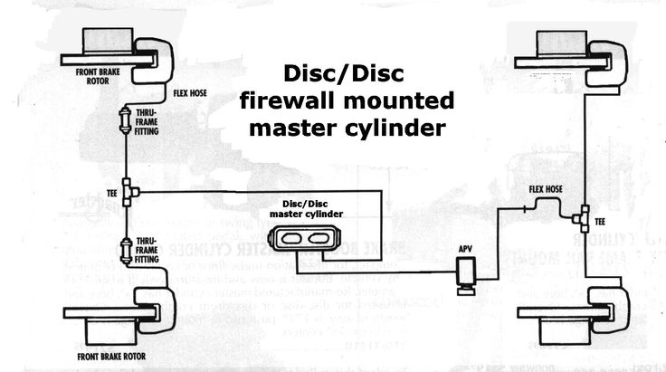
The 2005 Chevy Silverado typically uses a tandem master cylinder. "Tandem" refers to the fact that it has two separate hydraulic circuits. This is a critical safety feature. If one circuit fails, the other can still provide braking power, albeit reduced. Key components shown in the diagram include:
- Master Cylinder Reservoir: This holds the brake fluid. It's usually made of translucent plastic so you can easily check the fluid level.
- Master Cylinder Body: The main housing containing the pistons and springs. It's usually made of cast iron or aluminum.
- Primary Piston and Secondary Piston: These pistons are actuated by the brake pedal and push brake fluid into the brake lines. The diagram will illustrate their arrangement and how they generate hydraulic pressure.
- Primary and Secondary Hydraulic Circuits: Each piston connects to a separate hydraulic circuit, usually one for the front brakes and one for the rear brakes (or diagonally split circuits in some vehicles).
- Compensating Ports: Tiny ports within the master cylinder that allow brake fluid to return to the reservoir when the brakes are released, preventing excessive pressure buildup.
- Residual Pressure Valves (Rare in Modern Systems): In some older designs, these maintain a slight residual pressure in the brake lines to keep the brake shoes or pads close to the rotors/drums. However, they are less common in modern systems like the 2005 Silverado.
- Brake Lines: Depicted as lines connecting the master cylinder to the brake calipers and wheel cylinders.
Common Master Cylinder Specifications (Typical for 2005 Silverado):
- Bore Size: This affects the amount of fluid displaced per stroke of the piston. A larger bore size will move more fluid but require more pedal effort. Typically around 1 to 1 1/8 inches.
- Outlet Port Thread Size: Essential for replacing brake lines or fittings. Knowing this ensures you get the right parts.
- Fluid Type: Usually DOT 3 brake fluid, but always confirm the manufacturer's recommendation on the master cylinder itself or in your owner's manual. Using the wrong fluid can damage the seals!
Symbols and Conventions
Understanding the symbols used in the diagram is critical. Here's a breakdown:
- Lines:
- Solid Lines: Typically represent brake lines carrying brake fluid.
- Dashed Lines: May represent vacuum lines (for vacuum-assisted boosters) or electrical connections (for ABS systems).
- Arrows: Indicate the direction of fluid flow.
- Colors: Color coding can vary, but common conventions include:
- Red: High-pressure lines or components.
- Blue: Low-pressure lines or components.
- Black: Ground connections (for electrical components).
- Icons:
- Cylinders: Represent pistons within the master cylinder.
- Circles: Can represent ports, valves, or connections.
- Triangles: Often used for fluid reservoirs.
Remember, different diagrams might use slightly different conventions, so always refer to the legend or key provided with the specific diagram you're using.
How It Works
Here's the simplified explanation of how the 2005 Silverado master cylinder operates:
- When you press the brake pedal, the pushrod transfers force to the primary piston in the master cylinder.
- The primary piston moves forward, pressurizing the brake fluid in the primary hydraulic circuit.
- This pressure also acts on the secondary piston, which then pressurizes the brake fluid in the secondary hydraulic circuit.
- The pressurized brake fluid travels through the brake lines to the brake calipers (front brakes) and wheel cylinders (rear brakes).
- The pressure in the calipers forces the brake pads against the rotors, while the pressure in the wheel cylinders forces the brake shoes against the drums. This creates friction and slows the vehicle.
- When you release the brake pedal, the pistons return to their resting positions, and the brake fluid flows back to the master cylinder reservoir through the compensating ports.
The tandem design ensures that if one circuit fails (e.g., due to a leak), the other circuit can still provide braking force. This is a critical safety feature.
Real-World Use: Basic Troubleshooting Tips
The master cylinder diagram can be invaluable for troubleshooting brake problems. Here are a few examples:
- Spongy Brake Pedal: This could indicate air in the brake lines, a faulty master cylinder, or a leak in the system. The diagram can help you trace the brake lines and identify potential leak points.
- Brake Pedal Goes to the Floor: This often indicates a significant leak in the hydraulic system or a completely failed master cylinder. The diagram will help you locate the master cylinder and its connections to check for leaks.
- Brake Fluid Loss: Inspect the master cylinder reservoir and its connections for leaks. Also, check the brake lines, calipers, and wheel cylinders. The diagram will guide you to these components.
- One Brake Seems to Be Dragging: Could be a caliper issue, or a problem with the proportioning valve (if equipped separately on the 2005 model). The diagram helps you understand the relationship between the master cylinder and the individual brake components.
Important: Always bleed the brake system after replacing any hydraulic component, including the master cylinder. Bleeding removes air from the lines, ensuring proper brake function.
Safety Considerations
Working on brake systems involves some inherent risks. Brake fluid is corrosive and can damage paint and skin. Always wear safety glasses and gloves when handling brake fluid. Also, ensure the vehicle is properly supported on jack stands before working underneath it.
The master cylinder itself can be pressurized, even when the engine is off. Depressurize the system by pumping the brake pedal several times before disconnecting any brake lines.
If you're unsure about any aspect of brake repair, consult a qualified mechanic. Brakes are a critical safety system, and a mistake can have serious consequences.
Finally, remember that cleanliness is paramount when working with hydraulic systems. Even small amounts of dirt or debris can contaminate the brake fluid and damage components.
You now have a solid foundation for understanding the 2005 Chevy Silverado master cylinder diagram. Remember to always consult your vehicle's specific service manual for the most accurate and detailed information. You can download the 2005 Chevy Silverado Master Cylinder Diagram. Good luck and stay safe!