2005 Chevy Silverado Wiring Harness Diagram
Let's dive into the often-intimidating but absolutely essential world of wiring diagrams, specifically focusing on the 2005 Chevy Silverado. Understanding the wiring harness diagram for your Silverado isn't just for seasoned mechanics; it's a valuable tool for any intermediate car owner, modder, or DIY mechanic who wants to troubleshoot electrical problems, perform upgrades, or simply gain a deeper understanding of their truck's inner workings. We're going to break down the key components, explain the symbols and conventions, and provide some practical troubleshooting tips. Let's get started.
Purpose: Your Silverado's Electrical Roadmap
Why bother with a wiring diagram? There are several crucial reasons:
- Troubleshooting: The most common use. When something electrical goes wrong – a light doesn't work, the radio cuts out, or the engine misfires – the wiring diagram helps you trace the circuit, identify potential breaks or shorts, and pinpoint the faulty component.
- Repairs: After diagnosing a problem, the diagram shows you how to correctly reconnect wires after replacing a damaged component. It ensures you don't accidentally cross wires and cause further damage.
- Upgrades and Modifications: Planning to install a new stereo, alarm system, trailer brake controller, or aftermarket lighting? The wiring diagram is essential for tapping into the correct circuits and avoiding blown fuses or fried modules.
- Learning and Understanding: Even if you're not actively troubleshooting, studying the wiring diagram can give you a comprehensive understanding of how your Silverado's electrical system is structured and how its various components interact.
Think of it as the electrical blueprint for your truck. It's the key to unlocking its electrical secrets.
Key Specs and Main Parts of the Wiring Harness
The 2005 Silverado’s wiring harness is a complex network that distributes power and signals throughout the vehicle. It’s not a single, monolithic entity, but rather a collection of sub-harnesses, each responsible for specific systems. Some of the key areas covered in the wiring diagram include:
- Engine Management System (EMS): This section covers the wiring for the engine control module (ECM), sensors (like oxygen sensors, mass airflow sensor, coolant temperature sensor), injectors, ignition system, and related components. It's a critical section for diagnosing engine performance issues.
- Transmission Control System: For automatic transmissions, this section shows the wiring for the transmission control module (TCM), solenoids, and sensors that control shifting.
- Body Control System: This includes the wiring for lights (headlights, taillights, turn signals, interior lights), power windows, power locks, door chime, and other body-related electrical functions, often managed by the body control module (BCM).
- Instrument Panel: Wiring for gauges, warning lights, and the instrument cluster itself.
- Anti-lock Brake System (ABS): Wiring for the ABS module, wheel speed sensors, and related components.
- Airbag System: Wiring for the airbag control module, sensors, and airbags themselves. (Important Safety Note: Always disconnect the battery and wait at least 10 minutes before working on the airbag system to avoid accidental deployment.)
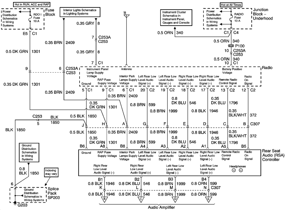
- Audio System: Wiring for the radio, speakers, amplifier (if equipped), and antenna.
- HVAC System: Wiring for the heating, ventilation, and air conditioning system, including the blower motor, compressor, and controls.
The diagrams often include connector views, showing the physical layout of the pins in each connector. This is invaluable when trying to identify and test specific wires.
Decoding the Symbols: Lines, Colors, and Icons
Wiring diagrams use a standardized set of symbols and conventions to represent electrical components and their connections. Understanding these symbols is crucial for interpreting the diagram correctly. Here's a breakdown of the most common elements:
- Lines: Solid lines represent wires. Dashed lines often represent shielded wires or control signals. The thickness of the line usually doesn't indicate wire gauge; it's simply for clarity.
- Colors: Each wire is identified by a color code, usually a two-letter abbreviation (e.g., BLK for black, RED for red, GRN for green, WHT for white, BLU for blue, YEL for yellow, ORG for orange, BRN for brown, GRY for gray). These colors help you identify the correct wire in the harness.
- Components: Symbols represent electrical components such as resistors (jagged line), capacitors (parallel lines), diodes (triangle with a line), relays (coil and switch), fuses (zigzag line in a rectangle), switches (line connecting to one or more terminals), and grounds (series of decreasing lines).
- Connectors: Connectors are represented by various shapes, often rectangles or circles, with lines indicating the wires entering and exiting the connector. Connector views show the pin layout.
- Grounds: Ground symbols indicate where a circuit connects to the vehicle's chassis, providing a return path for the current. Grounds are often a common point of failure, so knowing their locations is essential.
- Splices: Splices are points where multiple wires are joined together. They are often represented by a dot where the wires intersect.
Most diagrams include a legend or key that defines the symbols and abbreviations used. Always refer to the legend before attempting to interpret the diagram.
How It Works: Tracing the Circuit
A wiring diagram is essentially a map that shows the path of electrical current through a circuit. To use it effectively, you need to understand how to trace a circuit:
- Identify the Problem: Start with a specific symptom, such as a non-functioning headlight.
- Locate the Relevant Circuit: Find the section of the wiring diagram that corresponds to the headlight circuit.
- Trace the Power Source: Identify the power source (usually the battery) and follow the wire from the battery to the fuse or circuit breaker that protects the headlight circuit.
- Follow the Current Path: Trace the wire from the fuse to the headlight switch. From the switch, follow the wire to the headlight itself.
- Identify Ground Points: Locate the ground wire for the headlight and follow it to the chassis ground.
- Look for Breaks or Shorts: As you trace the circuit, look for potential points of failure, such as damaged wires, loose connections, corroded grounds, or faulty components (switch, fuse, headlight).
- Use a Multimeter: Use a multimeter to test for voltage, continuity, and resistance at various points in the circuit to pinpoint the location of the problem. Continuity refers to uninterrupted electrical pathway. Resistance refers to the opposition to the flow of electrical current.
Real-World Use: Basic Troubleshooting Tips
Here are some practical troubleshooting tips using the wiring diagram:
- Start with the Basics: Check the fuse first. A blown fuse is often the simplest explanation for an electrical problem. Use the wiring diagram to locate the fuse box and identify the correct fuse for the affected circuit.
- Check Grounds: Poor grounds are a common cause of electrical problems. Make sure the ground connections are clean, tight, and free of corrosion. Use the wiring diagram to locate the ground points for the affected circuit.
- Inspect Connectors: Loose or corroded connectors can cause intermittent problems. Check the connectors in the circuit for damage or corrosion. Clean the terminals with electrical contact cleaner and ensure they are properly seated.
- Use a Test Light or Multimeter: A test light or multimeter can be used to check for voltage and continuity in the circuit. This helps you determine if power is reaching the component and if the circuit is complete.
- Isolate the Problem: If you suspect a faulty component, try to isolate it from the circuit. For example, you can disconnect the headlight and test it directly with a 12V power source to see if it works.
Safety First: Handling Risky Components
Working with automotive electrical systems can be dangerous if you don't take proper precautions. Here are some key safety tips:
- Disconnect the Battery: Always disconnect the negative battery terminal before working on any electrical system. This prevents accidental shorts and potential damage to the vehicle's electronics.
- Airbag Systems: Never probe or tamper with airbag wiring unless you are a qualified technician. Accidental deployment of an airbag can cause serious injury. Disconnect the battery and wait at least 10 minutes before working on the airbag system.
- High-Voltage Components: Be aware of any high-voltage components, such as the ignition system. Avoid touching these components while the engine is running.
- Use Proper Tools: Use insulated tools and wear safety glasses when working on electrical systems.
- Consult a Professional: If you are not comfortable working on electrical systems, consult a qualified mechanic.
Important: Always refer to the vehicle's service manual for specific safety instructions and procedures.
With a little patience and the right information, you can confidently use the 2005 Chevy Silverado wiring harness diagram to diagnose and repair electrical problems, perform upgrades, and gain a deeper understanding of your truck. Remember to always prioritize safety and consult a professional if you're unsure about any procedure.
We have a copy of the 2005 Chevy Silverado wiring harness diagram available for download. This comprehensive diagram will provide you with the detailed information you need to tackle your Silverado's electrical challenges.