2005 Chevy Trailblazer Rear Fuse Box Diagram
Alright, let's dive into the rear fuse box diagram for a 2005 Chevy Trailblazer. Whether you're diagnosing electrical gremlins, planning modifications, or simply trying to understand your vehicle's wiring, having a solid grasp of this diagram is crucial. This isn't just some abstract drawing; it's your roadmap to resolving electrical issues and ensuring your Trailblazer keeps running smoothly.
Purpose of the Rear Fuse Box Diagram
Why bother with this diagram? Simple: it’s essential for electrical troubleshooting and modifications. Imagine you have a blown taillight, a malfunctioning trailer wiring connection, or want to install an aftermarket amplifier. Without the diagram, you're essentially fumbling in the dark. The diagram allows you to:
- Identify the correct fuse or relay for a specific circuit.
- Trace wiring paths to pinpoint shorts or open circuits.
- Plan and execute modifications safely and correctly, without damaging your vehicle's electrical system.
- Understand the protection scheme for different components.
Key Specs and Main Parts
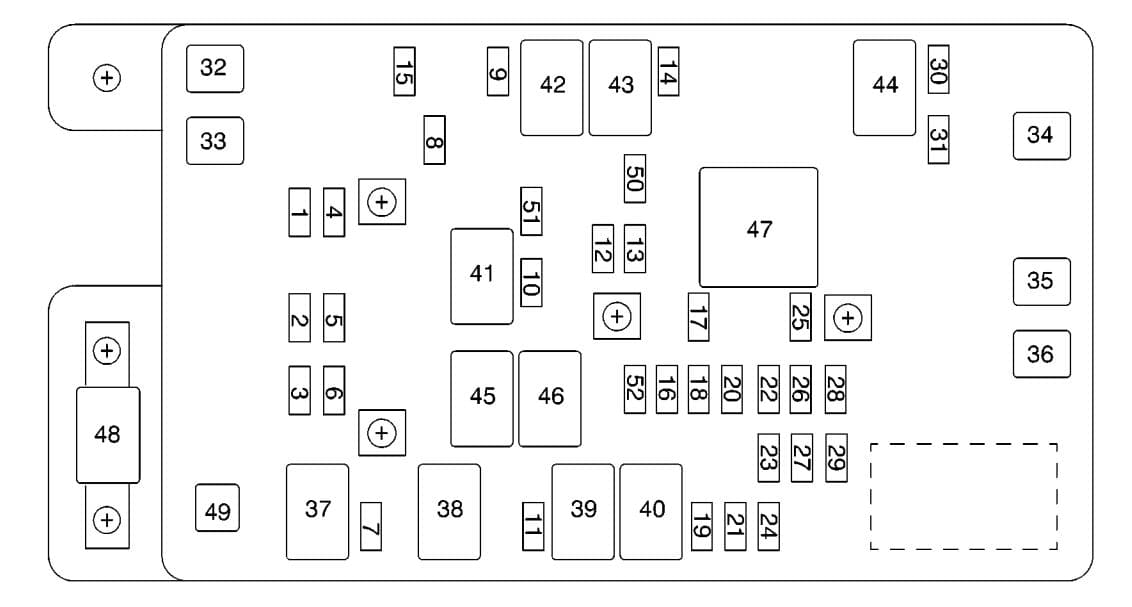
The rear fuse box on a 2005 Trailblazer is typically located in the cargo area, usually behind an access panel on the driver's side. It houses a collection of fuses and relays designed to protect various electrical circuits in the rear of the vehicle.
Fuses
Fuses are sacrificial devices designed to protect circuits from overcurrent. When the current exceeds the fuse's rating, the internal element melts, breaking the circuit and preventing damage to components. The fuse rating is measured in Amperes (A). Common ratings you'll find include 5A, 10A, 15A, 20A, 25A, and 30A. It's important to always replace a blown fuse with one of the same amperage rating. Using a higher amperage fuse can bypass the circuit protection and lead to serious damage or even a fire.
Relays
Relays are electrically operated switches. They use a small current to control a larger current. The Trailblazer uses various relays for functions like the rear wiper, rear defogger, and trailer lighting. A relay consists of a coil, which when energized, creates a magnetic field that pulls a switch (the armature) to connect or disconnect a circuit. Understanding relay operation is key to diagnosing issues with these systems.
Wiring Harnesses and Connectors
The diagram will show the wiring harnesses and connectors associated with the rear fuse box. These connectors ensure proper electrical connections between the fuse box and the various components in the rear of the vehicle. Identifying the correct connector for a specific circuit is crucial for testing and troubleshooting.
Understanding the Symbols
A fuse box diagram isn't just a random collection of lines and boxes. Each symbol has a specific meaning. Here's a breakdown of common symbols:
- Straight Lines: Represent wires. The thickness of the line doesn't necessarily indicate wire gauge, but often thicker lines represent power feeds.
- Dashed Lines: May indicate a ground connection or a shielded wire.
- Fuses: Typically represented by a squiggly line inside a rectangle. The amperage rating is usually labeled next to the symbol.
- Relays: Shown as a coil connected to a switch. The coil symbol usually looks like a looped wire, and the switch is depicted as a mechanical switch (often an angled line connected to a contact).
- Connectors: Represented by circles, squares, or other geometric shapes. Connector numbers are often included for identification.
- Ground Symbols: Several variations exist, usually resembling a downward-pointing rake or a series of horizontal lines. These indicate the grounding point for the circuit.
- Color Coding: Wires are often color-coded in the diagram. Common colors include red (power), black (ground), and various other colors for signal wires. The legend accompanying the diagram will explain the color codes.
The color of the wires is crucial. For example, a pink wire might be for the fuel pump circuit, while a dark green wire might be for the reverse lights. Always refer to the legend to confirm the color coding.
How It Works: The Circuit Path
The diagram illustrates the path of electricity through each circuit. Typically, power originates from the battery, travels through a fuse or relay for protection or control, and then to the component (e.g., taillight, rear wiper motor). A ground wire completes the circuit, returning the electricity to the battery. Understanding this flow is essential for troubleshooting.
For instance, let's say you have a blown fuse for the trailer lights. The diagram will show you the path: Battery -> Fuse Box -> Trailer Light Connector -> Trailer Lights -> Ground. By understanding this path, you can use a multimeter to check for voltage at the fuse, at the trailer light connector, and then check the ground connection. A lack of voltage or a poor ground indicates where the problem lies.
Real-World Use: Basic Troubleshooting Tips
Here's how you can use the diagram to troubleshoot common electrical problems:
- Identify the Problem: Pinpoint the malfunctioning component (e.g., license plate light, rear window defogger).
- Consult the Diagram: Locate the fuse or relay associated with the component.
- Check the Fuse: Visually inspect the fuse for a broken element. Use a multimeter to confirm continuity (resistance of near zero ohms) across the fuse.
- Test the Relay: If the fuse is good, test the relay. You can often swap it with an identical relay from another non-critical circuit to see if the problem resolves. Alternatively, you can use a multimeter to test the relay's coil and switch.
- Trace the Wiring: If the fuse and relay are good, trace the wiring path from the fuse box to the component, looking for damaged wires, loose connections, or shorts to ground. Use your multimeter to check for voltage and continuity along the way.
For example, if your rear window defogger isn't working: Check the fuse labeled "RR DEFOG." If it's blown, replace it and see if it blows again. If it continues to blow, there's likely a short circuit in the defogger grid or wiring. If the fuse is good, check the relay. If the relay is good, use the diagram to trace the wiring from the relay to the defogger grid and look for breaks or shorts.
Safety Precautions
Working with automotive electrical systems can be dangerous. Always observe the following safety precautions:
- Disconnect the Battery: Before working on any electrical circuit, disconnect the negative terminal of the battery. This prevents accidental shorts and electrical shock.
- Use Proper Tools: Use insulated tools designed for automotive electrical work.
- Be Careful with Shorts: Avoid creating short circuits, as they can damage components and cause fires.
- Don't Modify Fuses: Never replace a fuse with one of a higher amperage rating or bypass a fuse altogether. This can create a serious fire hazard.
- Be Aware of SRS Components: Be especially cautious when working near the supplemental restraint system (SRS) components (airbags). Improper handling can cause accidental deployment.
The most risky components are those carrying the most current, particularly those associated with the starting and charging systems. Be extra careful when working around the battery, alternator, and starter motor.
Conclusion
Mastering the rear fuse box diagram for your 2005 Chevy Trailblazer empowers you to tackle a wide range of electrical repairs and modifications with confidence. By understanding the symbols, circuits, and safety precautions, you can save money on costly repairs and personalize your vehicle to your liking. Remember to always consult the diagram and follow proper safety procedures.
We have the complete, high-resolution diagram for the 2005 Chevy Trailblazer rear fuse box available for download. It's a valuable resource that will make troubleshooting and modifying your vehicle's electrical system much easier.