2005 Chrysler 300 Fuse Box Diagram In Trunk
Alright, let's dive into the 2005 Chrysler 300's rear fuse box, specifically the one located in the trunk. Understanding this fuse box diagram is crucial for several reasons, from simple bulb replacements to diagnosing more complex electrical issues. This isn't just a visual aid; it's your roadmap to troubleshooting and maintaining the electrical integrity of your 300's rear systems.
Purpose of Understanding the Trunk Fuse Box
Why bother learning about this fuse box? The most obvious reason is for repairs. A blown fuse can disable anything from your tail lights to your rear window defogger. Identifying the faulty fuse quickly saves you time and money compared to a trip to the mechanic. Second, it's invaluable for modifications. If you're adding aftermarket accessories like a subwoofer or upgraded lighting, knowing which circuits are available and their amperage ratings prevents overloading and potential damage. Lastly, even for general learning about automotive electrical systems, the fuse box diagram provides a practical entry point to understanding how different components are powered and protected.
Key Specs and Main Parts
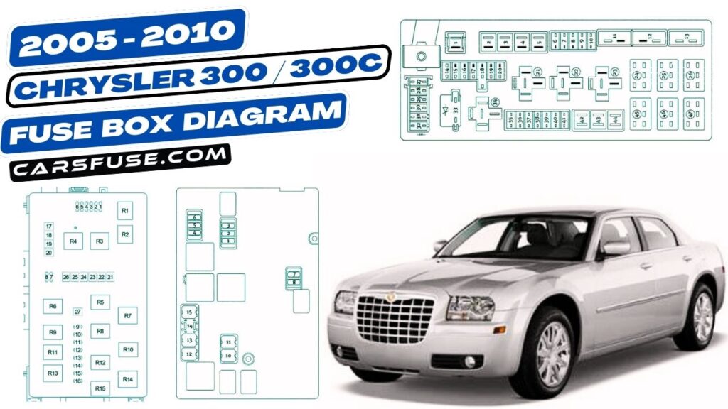
The rear fuse box, officially called the Power Distribution Center (PDC) in Chrysler terminology, is typically located in the trunk, often behind a trim panel on either the left or right side. It's a rectangular plastic enclosure containing a collection of fuses, relays, and sometimes circuit breakers. Here's a breakdown of the key elements:
- Fuses: These are the sacrificial links that protect circuits from overcurrent. They contain a thin wire that melts and breaks the circuit when the current exceeds its rating. Fuses are rated in amperes (amps or A), indicating the maximum current they can handle. Common ratings in this fuse box include 5A, 10A, 15A, 20A, 25A, and 30A.
- Relays: Relays are electrically operated switches that control high-current circuits using a low-current signal. They're used to switch on and off components like the rear window defogger, fuel pump, or horn. Relays are usually identified by their function and sometimes have a part number stamped on them.
- Circuit Breakers: Similar to fuses, but resettable. If an overcurrent condition occurs, the breaker trips, interrupting the circuit. Once the overload is removed, the breaker can be reset, often automatically or manually. They are less common than fuses in this fuse box.
- Fuse Puller: A small plastic tool included in the fuse box for safely removing fuses without damaging them or the surrounding connectors.
- Diagram Label: This is usually a sticker located on the inside of the fuse box cover or sometimes adjacent to the fuse box itself. It's the most important part, as it identifies the function and amperage rating of each fuse and relay.
Understanding the Symbols and the Diagram
The fuse box diagram isn't just a random assortment of squares and rectangles; it's a symbolic representation of the electrical circuit layout. Learning to "read" the diagram is crucial for effective troubleshooting.
- Fuses: Usually depicted as small rectangles with a number indicating the amperage rating (e.g., "10A"). The orientation of the rectangle doesn't typically matter.
- Relays: Usually shown as larger squares or rectangles with internal symbols representing the relay's coil and switch contacts. The diagram may also include a description of the relay's function (e.g., "Rear Defog Relay").
- Lines: Solid lines represent the electrical wiring connecting the fuses and relays to the various components. The thickness of the line generally does *not* represent wire gauge.
- Colors: Most diagrams *do not* show wire colors. Wire colors are documented in the service manual for the vehicle, which is separate from the fuse box diagram. However, sometimes the fuse box itself might have colored connectors to aid in identifying specific circuits.
- Icons: Icons represent the components that are powered by the fuses and relays. For example:
- A light bulb icon might represent the tail lights or brake lights.
- A window with wavy lines might represent the rear window defogger.
- An outlet symbol represents a power outlet.
- Location Indicators: The diagram might use abbreviations or codes to indicate the specific location of components within the vehicle. This is particularly helpful when dealing with multiple fuse boxes.
How It Works: Electrical Flow
The fuse box is essentially a distribution point for electrical power. The battery provides the initial electrical source. Wires carry this power to the front fuse box and the rear fuse box (PDC). When the ignition switch is turned on, or a particular system is activated (like the headlights), power flows through the appropriate fuses and relays in the fuse box. If a fuse blows, it interrupts this flow, preventing the component from functioning. Relays act as gatekeepers, allowing a small electrical signal to control the flow of power to high-current devices.
Real-World Use: Basic Troubleshooting Tips
Here’s how you can use the fuse box diagram to troubleshoot common electrical problems:
- Identify the Symptom: Determine which component isn't working (e.g., the rear window defogger isn't heating).
- Consult the Diagram: Locate the fuse or relay associated with that component in the rear fuse box diagram.
- Inspect the Fuse: Physically examine the fuse. A blown fuse will have a broken filament inside. You can also use a multimeter set to continuity mode to check if the fuse is good (it should show continuity, meaning current can flow through it).
- Replace the Fuse: If the fuse is blown, replace it with a new fuse of the exact same amperage rating. Using a higher amperage fuse can overload the circuit and cause damage or even a fire.
- Test the Component: After replacing the fuse, test the component to see if it's now working.
- If the Fuse Blows Again: If the new fuse blows immediately or shortly after being replaced, there's likely a short circuit in the wiring or a fault within the component itself. Further diagnosis is required, potentially involving wire tracing and component testing.
- Relay Testing: Relays are a little harder to test without specific tools. You can try swapping the relay with an identical one from a less critical system (e.g., swapping the rear defogger relay with the horn relay) to see if the problem moves with the relay.
Safety Considerations
Working with automotive electrical systems involves inherent risks. Here are some crucial safety precautions:
- Disconnect the Battery: Before working on the fuse box or any electrical components, disconnect the negative (black) battery terminal to prevent accidental shorts or shocks.
- Use the Correct Fuse Rating: Never use a fuse with a higher amperage rating than specified in the diagram. Doing so bypasses the protection and can lead to overheating, damage, or even a fire.
- Be Careful with Relays: Relays can get hot when operating. Allow them to cool down before handling them.
- Avoid Working in Wet Conditions: Water and electricity don't mix. Ensure the area is dry before working on the fuse box.
- High-Current Components: Be especially careful around components like the rear window defogger, which draw significant current. A short circuit in these circuits can be dangerous.
By understanding the 2005 Chrysler 300 trunk fuse box diagram, you can confidently tackle a wide range of electrical repairs and modifications. Remember to always prioritize safety and consult the vehicle's service manual for detailed wiring diagrams and component testing procedures.
We have a copy of the detailed 2005 Chrysler 300 Fuse Box Diagram that you can download. This diagram provides a visual representation of the fuse box layout, along with the amperage ratings and descriptions of each fuse and relay. This file is invaluable for troubleshooting electrical issues and performing modifications on your vehicle.