2005 Dodge Ram 1500 Exhaust System Diagram
Alright, let's dive into the exhaust system diagram for your 2005 Dodge Ram 1500. Understanding this layout is crucial, whether you're diagnosing a pesky rattle, planning an upgrade, or simply expanding your automotive know-how. This guide is designed to be your go-to resource, offering a clear, technical, yet approachable explanation. We've got the diagram itself available for download (details at the end!), but first, let's get you grounded in the fundamentals.
Purpose of the Exhaust System Diagram
Why bother with a diagram? Well, it’s invaluable for several reasons:
- Diagnostics: Pinpointing the exact location of a leak or damaged component becomes significantly easier. Instead of blindly poking around, you can trace the exhaust flow and identify potential problem areas quickly.
- Repair and Replacement: Whether you're replacing a rusty muffler or a cracked exhaust manifold, the diagram shows you how everything connects and where each part is located. This saves you time and frustration.
- Upgrades and Modifications: Thinking about installing a new cat-back system or headers? The diagram illustrates the existing setup, helping you plan your modifications and avoid compatibility issues.
- Learning and Understanding: For the mechanically inclined, the diagram provides a visual representation of the exhaust system's operation, deepening your understanding of how your truck works.
Key Specs and Main Parts
The 2005 Dodge Ram 1500, depending on the engine (3.7L V6, 4.7L V8, or 5.7L HEMI V8), has a slightly different exhaust system layout. However, the core components remain the same. Let's break them down:
- Exhaust Manifolds: These collect exhaust gases directly from the engine's cylinders. They're typically made of cast iron or, in some performance applications, stainless steel. Cracking is a common issue, leading to leaks and a loss of power.
- Catalytic Converters: Crucial for emissions control, the catalytic converter uses catalysts to convert harmful pollutants (hydrocarbons, carbon monoxide, and nitrogen oxides) into less harmful substances. Older Rams (especially if not maintained) can experience clogged or failing converters. This will definitely trigger your check engine light and degrade performance.
- Oxygen Sensors (O2 Sensors): Located before (upstream) and after (downstream) the catalytic converter, O2 sensors monitor the oxygen content in the exhaust stream. They provide feedback to the engine control unit (ECU) to optimize the air-fuel ratio. A faulty O2 sensor can negatively impact fuel economy and emissions.
- Exhaust Pipes: These connect the various components of the exhaust system, directing the flow of exhaust gases from the manifolds to the muffler. Pay attention to the pipe diameter – larger diameters generally offer better flow (but can also reduce backpressure if oversized).
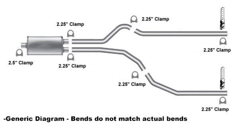
- Muffler: The muffler's primary function is to reduce noise. Various muffler designs exist, each with a different sound characteristic and flow rate. Common types include chambered, straight-through, and turbo mufflers.
- Resonator (Optional): Some Ram 1500s have a resonator, which further reduces noise and drone. It's usually located before the muffler.
- Tailpipe: The final section of the exhaust system, directing the exhaust gases away from the vehicle.
- Hangers and Brackets: These support the entire exhaust system, preventing it from vibrating and causing damage. Rusty or broken hangers are a common cause of exhaust rattles.
- Gaskets and Flanges: Located between components, gaskets and flanges create a seal to prevent exhaust leaks. These are consumable items and should be replaced whenever the exhaust system is disassembled.
Understanding the Diagram: Symbols and Lines
A typical exhaust system diagram uses a standardized set of symbols and line styles to represent different components and their connections. Here's a brief overview:
- Solid Lines: Generally represent the main exhaust pipes and connections between components. The thickness of the line might indicate the pipe diameter.
- Dashed Lines: Could represent vacuum lines or other auxiliary lines related to the exhaust system, such as those used for an EGR (Exhaust Gas Recirculation) system, if equipped.
- Boxes or Rectangles: Typically represent components like catalytic converters, mufflers, or resonators.
- Circles: Often used to represent O2 sensors or other sensors within the exhaust system.
- Arrows: Indicate the direction of exhaust flow.
- Labels: Each component should be clearly labeled with its name or a reference number that corresponds to a parts list.
The specific colors used in the diagram may vary depending on the source, but they often don't carry significant meaning beyond distinguishing different parts. Always refer to the diagram's legend or key for specific color interpretations.
How the Exhaust System Works
The exhaust system's primary function is to safely and efficiently remove combustion byproducts from the engine. Here's a simplified overview of the process:
- Exhaust gases are expelled from the engine's cylinders into the exhaust manifolds.
- The manifolds collect these gases and direct them into the catalytic converter(s), where harmful pollutants are converted into less harmful substances.
- O2 sensors monitor the oxygen levels in the exhaust stream, providing feedback to the ECU to optimize fuel delivery.
- The exhaust gases then flow through the exhaust pipes to the muffler (and possibly a resonator).
- The muffler reduces the noise level of the exhaust.
- Finally, the exhaust gases exit the vehicle through the tailpipe.
The system also plays a role in engine performance. Backpressure, the resistance to exhaust flow, can affect engine power. While some backpressure is necessary for optimal low-end torque, excessive backpressure can restrict engine performance, particularly at higher RPMs.
Real-World Use: Basic Troubleshooting Tips
Here are some common exhaust system problems and how the diagram can help you diagnose them:
- Exhaust Leak: A hissing or popping sound, often accompanied by a sulfurous smell, is a telltale sign. Use the diagram to visually inspect the exhaust system for cracks, holes, or loose connections. Pay close attention to joints between components.
- Rattling Noise: Could be caused by a loose heat shield, a broken hanger, or a detached internal component within the muffler. The diagram helps you locate the hangers and shields for inspection.
- Check Engine Light: If the check engine light illuminates, have the code scanned. Common exhaust-related codes involve O2 sensors or catalytic converter efficiency. The diagram shows the location of the O2 sensors, facilitating replacement.
- Poor Fuel Economy: Can be caused by a faulty O2 sensor or a clogged catalytic converter. Use the diagram to verify the O2 sensor connections and visually inspect the catalytic converter for damage.
Safety Considerations
Working on the exhaust system can be dangerous. Here are some important safety precautions:
- Hot Exhaust: The exhaust system gets extremely hot. Always allow the engine to cool completely before working on it. Even after the engine is off, the exhaust system can remain hot for a considerable amount of time.
- Jack Stands: Never work under a vehicle supported only by a jack. Use sturdy jack stands to support the vehicle safely.
- Eye Protection: Wear safety glasses to protect your eyes from debris.
- Gloves: Wear gloves to protect your hands from sharp edges and hot surfaces.
- Carbon Monoxide: Exhaust gases contain carbon monoxide, a deadly gas. Always work in a well-ventilated area. Never run the engine indoors or in a confined space.
- Oxygen Sensors: When working around the heated O2 sensors, use caution since the sensors have a heating element that can be very hot.
Always disconnect the negative terminal of the battery before working on any electrical components, including O2 sensors.
By following these safety precautions, you can minimize the risk of injury while working on your exhaust system.
Now that you have a solid understanding of the 2005 Dodge Ram 1500 exhaust system and how to utilize the diagram, you're well-equipped to tackle repairs, upgrades, or simply expand your automotive knowledge. Remember to always prioritize safety and consult a professional mechanic if you're unsure about any aspect of the job.
As mentioned earlier, we have the complete 2005 Dodge Ram 1500 exhaust system diagram available for download. [Instructions/Link to download here]