2005 Dodge Ram 1500 Front Suspension Diagram
So, you're tackling the front suspension on your 2005 Dodge Ram 1500? Excellent! Knowing the ins and outs of this system is crucial for everything from diagnosing that annoying clunk to performing upgrades that'll improve your ride and handling. This article will break down the front suspension diagram, explain its components, and give you the knowledge to confidently work on your truck. We even have the full diagram available for download later on.
Purpose of the Front Suspension Diagram
Think of the front suspension diagram as a roadmap to your truck's front-end. It's a detailed visual representation of all the components, their relationships, and how they function together. Why is this important? Well, it's indispensable for:
- Diagnosis: Pinpointing the source of noises, vibrations, or handling issues. A diagram helps you trace the problem back to the faulty part.
- Repairs: Understanding the assembly order and torque specifications before tearing anything apart saves you time and prevents mistakes.
- Modifications: Planning lifts, leveling kits, or performance upgrades requires a thorough understanding of the existing suspension geometry.
- Learning: Gaining a deeper understanding of automotive engineering and how your vehicle works.
- Parts Identification: Quickly and accurately identifying the correct replacement parts.
Key Specs and Main Parts of the 2005 Dodge Ram 1500 Front Suspension
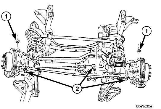
The 2005 Dodge Ram 1500 utilizes an independent front suspension, specifically a short-and-long-arm (SLA) design, also known as double wishbone suspension. This design is known for its good handling characteristics and ride quality. Here are the key parts you'll find on the diagram:
- Upper Control Arm: Connects the steering knuckle to the frame. It controls the upper portion of the wheel's movement.
- Lower Control Arm: Connects the steering knuckle to the frame, controlling the lower portion of the wheel's movement. Generally more robust than the upper arm due to higher load.
- Steering Knuckle (or Spindle): The pivoting point that houses the wheel hub/bearing assembly and connects to the control arms and steering linkage.
- Wheel Hub/Bearing Assembly: Allows the wheel to rotate smoothly on the spindle. Contains the bearings that reduce friction.
- Coil Spring: Absorbs vertical impacts and supports the weight of the vehicle. It's a torsion spring, storing energy by twisting when compressed.
- Shock Absorber (Damper): Controls the rate of compression and rebound of the coil spring, preventing excessive bouncing and oscillations. Critical for handling and stability.
- Upper Ball Joint: A spherical bearing that connects the upper control arm to the steering knuckle, allowing for articulation.
- Lower Ball Joint: A spherical bearing that connects the lower control arm to the steering knuckle. Typically carries more load than the upper ball joint.
- Tie Rod End (Inner and Outer): Part of the steering linkage that connects the steering rack to the steering knuckle, translating steering wheel input into wheel movement.
- Sway Bar (Stabilizer Bar): Connects the left and right sides of the suspension, reducing body roll during cornering.
- Sway Bar End Links: Connect the sway bar to the control arms or struts.
- Frame: The structural backbone of the vehicle, providing mounting points for all suspension components.
Key Specs: Knowing the torque specifications for each bolt is crucial. These are not always included on the diagram itself, but rather in a separate service manual. Always consult the manual before tightening any suspension component. Also, the ride height specifications are important for diagnosing sagging springs or other suspension problems. The diagram can help you identify the points to measure ride height.
Understanding the Symbols on the Diagram
Suspension diagrams often use standardized symbols to represent different components and connections. While the exact symbology can vary slightly between diagrams, here are some common conventions:
- Solid Lines: Typically represent fixed components or rigid connections, such as control arms, the frame, or the steering knuckle.
- Dashed Lines: Often indicate hidden components or areas that are located behind other parts. They can also represent lines of action or movement.
- Circles/Spheres: Usually indicate ball joints or pivot points. Their size and shading may represent the type of joint.
- Spring Symbols: A coiled line with arrow ends pointing in. This indicates a spring, coil spring or other springing device.
- Fastener Symbols: Circles with crosses are often used to represent bolts, nuts, or other fasteners. The diagram may include callouts to specific bolt sizes and grades.
- Colors: Some diagrams may use color coding to differentiate between different systems or materials. For example, hydraulic lines for power steering might be colored blue, while electrical wiring might be colored yellow or green.
- Arrows: Indicate the direction of movement, forces, or fluid flow.
How the 2005 Dodge Ram 1500 Front Suspension Works
In essence, the SLA suspension works by allowing each front wheel to move independently, which improves ride quality and handling. When the wheel encounters a bump, the coil spring compresses, absorbing the impact energy. The shock absorber dampens the spring's oscillations, preventing the vehicle from bouncing excessively. The control arms guide the wheel's movement, keeping it perpendicular to the road surface for optimal tire contact. The sway bar resists body roll during cornering by transferring some of the suspension load from one side of the vehicle to the other.
The steering system connects to the steering knuckle via the tie rod ends. When you turn the steering wheel, the steering rack moves laterally, pushing or pulling on the tie rods, which in turn steer the wheels. The ball joints allow the steering knuckle to pivot and articulate smoothly.
Real-World Use: Basic Troubleshooting Tips
Here are a few common issues you might encounter and how the diagram can help you diagnose them:
- Clunking Noise: A clunking noise, especially when going over bumps, is often caused by worn ball joints, tie rod ends, or sway bar end links. The diagram will show you the location of these components, allowing you to inspect them for excessive play or looseness.
- Wandering Steering: Wandering steering can be caused by worn tie rod ends, ball joints, or a misaligned suspension. The diagram can help you identify which components might be contributing to the problem.
- Uneven Tire Wear: Uneven tire wear can be caused by a misaligned suspension, worn ball joints, or bent control arms. The diagram can help you identify the components that need to be inspected.
- Sagging Suspension: A sagging suspension on one side of the vehicle can be caused by a broken or weakened coil spring. The diagram will show you the location of the coil spring, allowing you to inspect it for damage.
Remember: Always perform a thorough visual inspection before replacing any parts. Look for signs of wear, damage, or looseness. A good starting point is to jack up the truck (safely!) and try to wiggle each wheel. Excessive play indicates a problem with the wheel bearings, ball joints, or tie rod ends.
Safety Precautions
Working on the front suspension can be dangerous, so always take the following precautions:
- Use Jack Stands: Never work under a vehicle supported only by a jack. Always use properly rated jack stands.
- Wear Safety Glasses: Protect your eyes from debris and flying objects.
- Disconnect the Battery: Disconnect the negative battery cable to prevent accidental electrical shocks.
- Compress Coil Springs Carefully: Coil springs store a tremendous amount of energy. Use a proper coil spring compressor to safely compress and remove them. Improper use of a spring compressor can result in serious injury or death. This is probably the most dangerous part of the job.
- Torque to Specification: Always tighten fasteners to the manufacturer's specified torque. Using the wrong torque can lead to component failure or damage.
- Get an Alignment: After replacing any suspension components, it's essential to have the vehicle aligned by a qualified technician.
Specifically regarding the coil spring: this component is under immense pressure. Never attempt to disassemble the suspension without properly compressing the coil spring first using a dedicated spring compressor tool. If you are uncomfortable with this process, it's best to leave it to a professional.
This article provides a foundation for understanding the front suspension of your 2005 Dodge Ram 1500. Combined with the actual diagram, it's a powerful tool for maintaining and repairing your truck. Speaking of which, we have the full, detailed diagram ready for you to download. It includes all the part numbers and detailed schematics to help you get the job done right.
Now, go forth and conquer that front suspension...safely and effectively!