2005 Dodge Ram Stereo Wiring Diagram
Understanding the 2005 Dodge Ram stereo wiring diagram is crucial for anyone looking to upgrade their audio system, troubleshoot electrical issues, or perform any kind of DIY work involving the radio and speaker setup. This article will provide a detailed breakdown of the diagram, equipping you with the knowledge to confidently tackle your project.
Purpose of the Stereo Wiring Diagram
The stereo wiring diagram serves as a roadmap to the entire audio system. It's not just a pretty picture; it's a critical tool for several reasons:
- Upgrading Your Stereo: When installing a new head unit (the main radio unit), you'll need to know which wires connect to which functions – power, ground, speakers, etc. The diagram eliminates guesswork and prevents damage to your vehicle's electrical system.
- Troubleshooting Audio Issues: Is one of your speakers not working? Is the radio losing power intermittently? The wiring diagram helps you trace the signal path to identify the faulty component, whether it's a blown fuse, a damaged wire, or a malfunctioning speaker.
- Installing Aftermarket Amplifiers and Speakers: Adding an amplifier or upgrading your speakers requires understanding the impedance (resistance to AC current) and wiring configurations to ensure proper compatibility and optimal sound quality. The diagram helps you tap into the correct speaker wires and avoid overloading the factory system.
- Learning Automotive Electrical Systems: Even if you're not planning any immediate modifications, studying the wiring diagram provides valuable insight into how automotive electrical systems are designed and function.
Key Specs and Main Parts of the 2005 Dodge Ram Stereo System
Before diving into the diagram itself, let's outline the key components of the 2005 Dodge Ram's stereo system:
- Head Unit: The brain of the system. It receives radio signals, plays CDs, and controls the volume, tone, and other settings. The 2005 Ram came with several head unit options, including single-DIN (standard size) and double-DIN (larger size) units, some with CD players, cassette players, or satellite radio capabilities.
- Speakers: Located in the doors, dashboard, and sometimes the rear deck. The 2005 Ram typically features a four-speaker system (two front, two rear), but premium trims might include six or more speakers with separate tweeters (high-frequency speakers).
- Antenna: Receives radio signals. Usually located on the roof or fender.
- Wiring Harness: A bundle of wires that connects the head unit to the rest of the vehicle's electrical system, including the speakers, power source, and ground.
- Amplifier (Optional): Some premium audio systems include a separate amplifier to boost the signal to the speakers.
Common 2005 Dodge Ram Audio System Features:
- CD player
- AM/FM radio
- Cassette player (depending on trim level)
- Steering wheel audio controls (depending on trim level)
- Possible amplifier connection
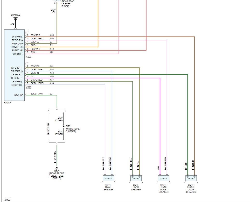
Decoding the Symbols and Conventions
Understanding the symbols and conventions used in the wiring diagram is essential for interpreting it correctly. Here are some common elements:
- Lines: Represent wires. The thickness of the line might indicate the wire gauge (thickness).
- Colors: Each wire is assigned a specific color, which is indicated on the diagram using abbreviations (e.g., "RD" for red, "BK" for black, "WH" for white). Always double-check the actual wire color in your vehicle to confirm.
- Ground Symbol: Usually looks like a series of downward-facing triangles. Indicates a connection to the vehicle's chassis, providing a return path for the electrical current.
- Speaker Symbol: Resembles a cone. Indicates the connection point for each speaker.
- Fuse Symbol: A wavy line enclosed in a rectangle. Protects the circuit from overcurrent.
- Connectors: Shown as boxes or circles where wires join together. These are often labeled with connector numbers.
- Splices: Indicated by a dot where two or more wires connect.
Color codes can vary slightly between different trim levels and production years, but here are some common ones you'll likely encounter:
- Red (RD): Typically used for constant power.
- Black (BK): Typically used for ground.
- Yellow (YL): Often used for switched power (power that is only on when the ignition is on).
- Blue (BL): Commonly used for the remote turn-on wire for an amplifier.
- White (WH): Frequently used for speaker wires.
- Green (GR): Frequently used for speaker wires.
- Gray (GY): Frequently used for speaker wires.
- Brown (BR): Frequently used for speaker wires.
Important Note: Always refer to the specific wiring diagram for your 2005 Dodge Ram, as variations may exist depending on the trim level and factory options. We have the correct file available for download.
How It Works: Tracing the Signal Path
The stereo system functions as follows:
- Power: The head unit receives power from the vehicle's battery through the power wire (typically red) and is grounded to the chassis via the ground wire (typically black). A fuse in the circuit protects the head unit from damage.
- Ignition Switch: A switched power wire (typically yellow) connected to the ignition switch provides power to the head unit when the ignition is turned on. This prevents the battery from being drained when the vehicle is off.
- Audio Signal: The head unit generates an audio signal from the radio, CD player, or other source.
- Amplification (Optional): If an amplifier is present, the audio signal is sent to the amplifier, which boosts the signal's power.
- Speaker Output: The amplified (or unamplified) audio signal is sent to the speakers via the speaker wires. Each speaker has two wires: a positive (+) wire and a negative (-) wire.
- Grounding: The negative (-) speaker wire provides a return path for the signal to the head unit or amplifier's ground.
By tracing these connections on the wiring diagram, you can understand how each component interacts with the others and identify potential points of failure.
Real-World Use: Basic Troubleshooting Tips
Here are some common issues you might encounter and how to troubleshoot them using the wiring diagram:
- No Power to the Radio: Check the fuses related to the radio (typically in the fuse box under the hood or inside the cabin). Use a multimeter to test if the power and ground wires are receiving voltage. Verify the ignition switch is providing power to the switched power wire.
- One Speaker Not Working: Check the speaker connections at both the speaker and the head unit (or amplifier). Use a multimeter to test the speaker wire for continuity (a complete electrical path). Swap the speaker with a known good speaker to isolate the problem.
- Static or Distortion: Check the speaker wires for damage or corrosion. Ensure the ground connections are secure. Test the speaker impedance with a multimeter.
- Radio Turns Off Intermittently: Check the power and ground connections for looseness. Look for frayed or damaged wires. The head unit itself might be failing.
Safety Considerations
Working with automotive electrical systems can be dangerous if proper precautions are not taken. Here are some important safety tips:
- Disconnect the Battery: Always disconnect the negative (-) terminal of the battery before working on any electrical components. This prevents accidental short circuits.
- Use Proper Tools: Use insulated tools designed for automotive electrical work.
- Never Cut Wires Without Knowing What They Do: Consult the wiring diagram before cutting any wires. Incorrect wiring can damage your vehicle's electrical system.
- Work in a Well-Lit Area: Ensure you have adequate lighting to see what you are doing.
- Be Aware of Airbag Systems: Avoid disturbing any wiring related to the airbag system, as this can cause accidental deployment. Airbags contain explosive components and can cause serious injury.
- Double-Check Your Work: Before reconnecting the battery, carefully double-check all connections to ensure they are secure and correct.
Always err on the side of caution. If you are unsure about any aspect of the repair, consult a qualified automotive electrician.
With the 2005 Dodge Ram Stereo Wiring Diagram, and the knowledge from this guide, you are ready to confidently tackle many of your audio system needs.