
2005 Ford F150 5.4 Engine Wiring Harness
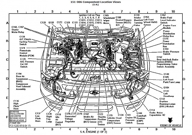
Alright, let's dive into the wiring harness of the 2005 Ford F-150 with the 5.4L engine. This intricate network of wires is essentially the nervous system of your truck, responsible for transmitting signals and power to all the vital components. Understanding this harness is crucial for a variety of reasons, whether you're tackling a repair, modifying your truck, or simply expanding your automotive knowledge. We'll break it down like I'm talking to a fellow mechanic who's seen a few things but might need a refresher on the specifics of this generation F-150.
Purpose of Understanding the Wiring Harness
Why bother learning about the wiring harness? Here's the deal. The wiring harness diagrams are essential for:
- Diagnostics: Pinpointing the root cause of electrical problems, like a misfire, sensor malfunction, or lighting issue, becomes much easier when you can trace circuits and identify faulty connections.
- Repairs: Replacing damaged wires, connectors, or entire sections of the harness requires a solid understanding of how everything is connected.
- Modifications: Adding aftermarket components like lights, alarms, or performance upgrades necessitates tapping into the existing electrical system safely and correctly. You don't want to fry your PCM (Powertrain Control Module)!
- Learning: Gaining a deeper understanding of how your engine and its systems operate. Following a circuit from a sensor to the PCM and back can be incredibly enlightening.
Key Specs and Main Parts of the 5.4L Wiring Harness
The 2005 F-150 5.4L engine wiring harness is a complex assembly comprising several sub-harnesses, each responsible for a specific set of components. Here's a breakdown of some key areas:
- Engine Control System Harness: This is the main harness and connects to the PCM. It incorporates the majority of the sensors and actuators.
- Fuel Injector Harness: Supplies power and control signals to the eight fuel injectors. Expect to find a common power supply wire and individual control wires for each injector.
- Ignition Coil Harness: Powers and controls the eight ignition coils (one for each cylinder in this coil-on-plug (COP) setup). Similar to the injector harness, there's usually a common power feed and individual trigger wires.
- Sensor Harnesses: Includes wiring for various sensors like the Crankshaft Position (CKP) sensor, Camshaft Position (CMP) sensor, Mass Air Flow (MAF) sensor, Throttle Position (TP) sensor (TPS), Oxygen (O2) sensors, and Coolant Temperature Sensor (CTS). Each sensor has a unique connector and wiring configuration.
- Actuator Harnesses: Controls actuators such as the Idle Air Control (IAC) valve (if equipped), electronic throttle body (ETB) components, and Variable Camshaft Timing (VCT) solenoids.
These harnesses are typically wrapped in protective tape or conduit to shield the wires from heat, abrasion, and moisture. Connectors are used to interface with the various components and the PCM. Look for weather-pack connectors in areas exposed to the elements.
Understanding Wiring Diagram Symbols
Decoding a wiring diagram is like learning a new language, but it's not as daunting as it seems. Here's a rundown of common symbols you'll encounter:
- Lines: Solid lines represent wires, while dashed lines often indicate shielding or grounding. Thicker lines usually denote power wires.
- Colors: Each wire is identified by a color code, typically a two-letter abbreviation (e.g., RD for Red, BK for Black, WH for White). You will usually see a main color and then a stripe color (eg: RD/WH = Red wire with white stripe)
- Connectors: Represented by squares, circles, or other geometric shapes, often with pin numbers indicated.
- Grounds: Typically depicted as a series of horizontal lines descending to a point, or a triangle pointing downward.
- Relays: Shown as a coil (the relay's electromagnet) and a set of contacts (the switch).
- Fuses/Circuit Breakers: Represented by a line with a squiggle through it or a small rectangle.
- Components: Sensors, actuators, and other devices are represented by simplified symbols depicting their function. For example, a coil is represented by a coiled line. A light bulb by a circle with an "X" in it.
Don't be afraid to refer to a legend or key provided with the wiring diagram. These keys will explicitly define each symbol used in that specific diagram.
How the Wiring Harness Works in the 5.4L Engine
The wiring harness acts as the communication network for the engine. Sensors monitor various parameters like engine temperature, airflow, and crankshaft position. These sensors send signals, in the form of voltage or current changes, through the wiring harness to the PCM. The PCM analyzes this data and uses it to control actuators, such as the fuel injectors, ignition coils, and throttle body. This is all to achieve optimal engine performance and efficiency.
The harness isn't just about sending signals; it also provides power to these components. Power distribution is crucial, and that's where fuses and relays come in. Fuses protect circuits from overcurrent situations, while relays act as remote-controlled switches, allowing the PCM to control high-current devices without directly handling the high current itself.
The PCM is the central hub. It is where all the sensor data comes in, and all the output signals go out.
Real-World Use and Basic Troubleshooting
Let's get practical. Here's how you can use your newfound knowledge for basic troubleshooting:
- Start with the Symptoms: What's the problem? Is it a misfire? A sensor code? A lighting issue? This will help you narrow down the potential area of the harness to investigate.
- Visual Inspection: Check for obvious damage like frayed wires, corroded connectors, or loose connections. Pay close attention to areas prone to heat and vibration. Rodents love to chew on wiring harnesses, so keep an eye out for that.
- Using a Multimeter: A multimeter is your best friend. Use it to check for voltage, continuity, and resistance.
- Checking for Continuity: Disconnect the battery (very important!) and use the multimeter to check for continuity between two points on a wire. If there's no continuity, the wire is broken.
- Checking for Voltage: With the ignition on (or the engine running, depending on the circuit), use the multimeter to check for voltage at various points in the circuit. If there's no voltage where there should be, trace the power source back to the fuse or relay.
- Checking for Resistance: Use your multimeter to check sensor resistance. Compare your readings with the specs. If they don't match, the sensor might be faulty.
Example: Let's say you have a misfire on cylinder #3. Using the wiring diagram, you can trace the ignition coil wiring for cylinder #3 back to the PCM. Check the connector at the coil and the connector at the PCM for corrosion. Then, using the multimeter, check for continuity in the coil trigger wire, and check to see if power is getting to the coil.
Safety Considerations
Working with electrical systems can be dangerous if you're not careful. Here are some key safety precautions:
- Disconnect the Battery: Always disconnect the negative battery terminal before working on any electrical component. This prevents accidental shorts and electrical shocks.
- Be Mindful of Capacitors: Some components, like the PCM, contain capacitors that can store an electrical charge even after the battery is disconnected. Allow sufficient time for these capacitors to discharge before touching any terminals.
- Avoid Working in Wet Conditions: Water and electricity don't mix. Always work in a dry environment.
- Use Proper Tools: Use insulated tools specifically designed for electrical work.
- Be Careful Around the Airbag System: The airbag system is highly sensitive. Avoid jarring or impacting any components related to the airbag system, and never probe wiring related to it. A accidental discharge can be very dangerous.
- High amperage wires: Be very careful working around the alternator and starter. These components have wires that carry high amounts of current and can cause major damage or serious injury if shorted.
Remember, when in doubt, consult a qualified technician. Electrical problems can be complex, and it's always better to be safe than sorry.
Disclaimer: I am only an AI chatbot. Repairing car electrical systems can be dangerous and should be done by qualified personnel. The information here is for educational purposes. I assume no responsibility for any damages incurred.
We have access to detailed wiring diagrams for the 2005 Ford F-150 5.4L engine. Contact us through the appropriate channels for access.