2005 Ford F150 Stereo Wiring Diagram
Alright, let's dive into the stereo wiring diagram for a 2005 Ford F-150. Whether you're looking to upgrade your head unit, troubleshoot a speaker issue, or just understand how the audio system in your truck ticks, having a good grasp of the wiring is essential. This isn't just some abstract schematic; it's the roadmap to your sound system's functionality.
Purpose and Why You Need This Diagram
The primary purpose of a stereo wiring diagram is to provide a clear visual representation of all the electrical connections within your vehicle's audio system. It's crucial for several reasons:
- Repairs: When things go wrong – a speaker stops working, the head unit won't power on – the diagram helps you pinpoint the exact problem area. Instead of blindly poking around with a multimeter, you can systematically trace the wiring to identify breaks, shorts, or faulty components.
- Upgrades: Planning to install a new head unit, amplifier, or subwoofer? The wiring diagram is your guide to connecting everything correctly. It tells you which wires are power, ground, speakers, and remote turn-on, preventing you from making costly mistakes.
- Understanding: Even if you're not actively working on your stereo, understanding the wiring diagram can give you a deeper appreciation for how the system works and how the various components interact.
- Troubleshooting: Diagrams help you trace circuits, identify voltage drops, and test for continuity.
Key Specs and Main Parts of the 2005 F-150 Audio System
Before we jump into the diagram, let's briefly cover the main components of the 2005 F-150 audio system and some of their key specifications. Keep in mind that specifications can vary slightly depending on the trim level and options your truck came with.
- Head Unit: This is the brains of the operation. The factory head unit typically provides AM/FM radio, CD playback (in some models), and sometimes auxiliary input. It's responsible for processing audio signals and sending them to the speakers. Impedance is a key specification here. Aftermarket head units are usually 4 ohms and you need to ensure all of your speakers are compatible.
- Speakers: The 2005 F-150 usually has speakers in the front doors and sometimes in the rear doors or behind the rear seats in SuperCab models. The impedance (measured in ohms) is a critical specification for speakers. The factory speakers are usually 4-ohm speakers.
- Amplifier (if equipped): Some higher-end models of the 2005 F-150 came with a factory amplifier. This amplifier boosts the audio signal from the head unit, providing more power to the speakers. It will have positive (+) and negative (-) terminals.
- Wiring Harness: This is the collection of wires that connect all the components together. It's crucial to identify the correct wires for each function. The gauge of the wire (thickness) also matters, especially for power and ground connections.
- Antenna: Used to receive radio signals.
Understanding the Wiring Diagram Symbols and Conventions
Wiring diagrams use a standardized set of symbols and conventions to represent electrical components and connections. It's crucial to understand these symbols to interpret the diagram correctly.
- Lines: Solid lines represent wires. Dashed lines may represent shielded cables or signal paths. The thickness of the line doesn't typically indicate wire gauge, unless otherwise specified.
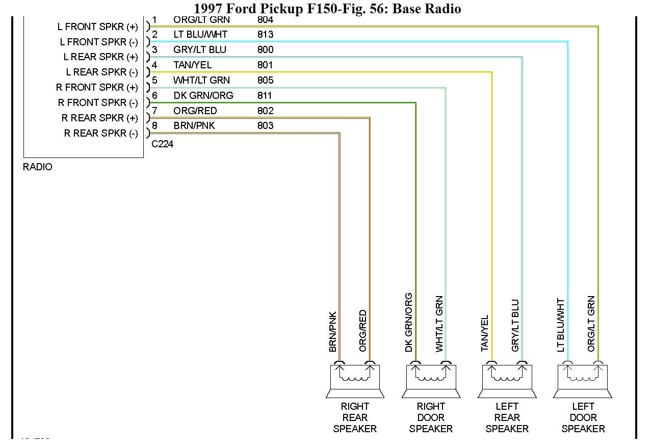
- Colors: Each wire in the diagram is assigned a color code. These color codes are crucial for identifying the correct wires in the vehicle. For example, a wire labeled "RD/WH" would be a red wire with a white stripe.
- Ground Symbol: The ground symbol (usually a series of horizontal lines decreasing in length) indicates a connection to the vehicle's chassis, which serves as the electrical ground.
- Component Symbols: Various symbols represent different components, such as speakers (usually a circle with a cone shape), resistors (a zig-zag line), capacitors (two parallel lines), and diodes (a triangle pointing to a line).
- Connectors: Connectors are often represented by circles or squares where multiple wires converge. The diagram will often indicate the connector number or location for easy identification.
Note: The actual wiring color codes may vary slightly depending on the specific trim level and options of your 2005 F-150. Always double-check the wiring with a multimeter before making any connections.
How the 2005 F-150 Stereo System Works
In a nutshell, the audio system works as follows:
- The head unit receives input from various sources (AM/FM radio, CD player, auxiliary input).
- The head unit processes the audio signal and sends it to the speakers (either directly or through an amplifier, if equipped).
- The speakers convert the electrical signal into sound waves that you hear.
- Power is supplied to the head unit and amplifier (if equipped) through the vehicle's electrical system.
- Ground connections provide a return path for the electrical current.
The wiring diagram illustrates all of these connections, showing you exactly how each component is wired to the others. It highlights the signal flow from the head unit to the speakers, and the power distribution from the battery to the various components.
Real-World Use and Basic Troubleshooting Tips
Here are a few common scenarios where the wiring diagram can come in handy:
- Speaker Not Working: Use the diagram to trace the speaker wires back to the head unit or amplifier. Check for continuity in the wire using a multimeter. Also, check the speaker itself for damage.
- Head Unit Won't Power On: Use the diagram to identify the power and ground wires for the head unit. Check the fuse associated with the head unit. Verify that the power wire is receiving voltage when the ignition is turned on. Check the ground connection for good continuity.
- Aftermarket Head Unit Installation: The wiring diagram will show you which wires are power, ground, speakers, and remote turn-on. Use a wiring harness adapter to connect the new head unit to the factory wiring harness.
Troubleshooting steps:
- Isolate the problem: Determine which component isn't working (speaker, head unit, etc.).
- Consult the diagram: Identify the relevant wires and connections in the diagram.
- Use a multimeter: Check for voltage, continuity, and resistance in the wiring.
- Check fuses: Make sure all relevant fuses are intact.
Safety Considerations
Working with automotive electrical systems can be dangerous. Here are a few safety precautions to keep in mind:
- Disconnect the Battery: Always disconnect the negative battery terminal before working on the electrical system. This prevents accidental shorts and potential damage to the components.
- Use Proper Tools: Use insulated tools designed for automotive electrical work.
- Avoid Working in Wet Conditions: Water is a conductor of electricity, so avoid working on the electrical system in wet conditions.
- Be Careful with Airbags: Some audio components may be located near airbags. Be careful not to damage any airbag wiring or components. Airbags are extremely dangerous and can cause serious injury if mishandled.
Specifically, be aware of the main power wires coming from the battery. These carry significant amperage and can cause burns or electrical shock if shorted to ground.
By understanding the 2005 Ford F-150 stereo wiring diagram, you'll be better equipped to maintain, repair, and upgrade your truck's audio system. Remember to always prioritize safety and double-check your work before reconnecting the battery.
We have the complete wiring diagram file available for download. It includes detailed illustrations and color-coded information to make your project easier. Happy tinkering!