2005 Grand Prix Radio Wiring Diagram
If you're diving into the audio system of your 2005 Pontiac Grand Prix, understanding its radio wiring is absolutely crucial. Whether you're upgrading the head unit, troubleshooting a speaker issue, adding an amplifier, or just trying to understand the electrical flow, a solid grasp of the wiring diagram is your best friend. This guide breaks down the 2005 Grand Prix radio wiring diagram, offering insights for DIY enthusiasts and experienced car mechanics alike.
Purpose of the Wiring Diagram
Why bother with a wiring diagram? Simple: it's the roadmap to your car's electrical system. Specifically, the radio wiring diagram allows you to:
- Diagnose problems: Identify broken wires, short circuits, or faulty components.
- Install aftermarket equipment: Connect new radios, amplifiers, speakers, or subwoofers without butchering your factory wiring.
- Perform repairs: Fix damaged wiring or replace faulty components correctly.
- Gain knowledge: Understand how the radio system integrates with the car's overall electrical infrastructure.
Key Specs and Main Parts of the 2005 Grand Prix Radio System
Before we delve into the diagram, let's familiarize ourselves with the key components:
- Head Unit (Radio): The central control unit, providing AM/FM reception, CD playback, and potentially other features like XM radio. It also includes the amplifier section.
- Speakers: Typically, the Grand Prix has front and rear speakers. The exact configuration may vary depending on trim level (e.g., with or without Monsoon premium sound).
- Antenna: Receives radio signals. It can be a fixed mast or embedded in the rear window.
- Wiring Harness: The bundle of wires connecting the radio to the car's electrical system and the speakers. Crucially, the harness includes connections for power (both constant and switched), ground, illumination, and speaker outputs.
- Grounding Points: Essential for completing the electrical circuits. Poor grounding can cause all sorts of audio problems.
- Amplifier (if equipped): The Monsoon system included a separate amplifier, typically located in the rear of the vehicle. If present, the wiring becomes slightly more complex, as the head unit outputs low-level signals to the amp, which then powers the speakers.
Understanding the Symbols in the Wiring Diagram
Wiring diagrams use a standardized set of symbols to represent electrical components and connections. Here's a breakdown of the common symbols you'll encounter:
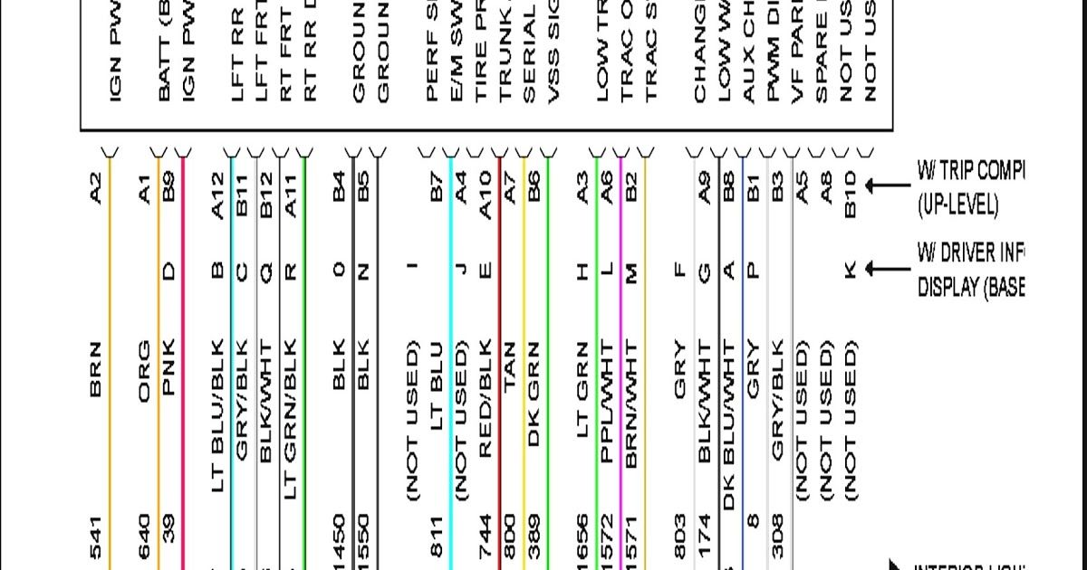
- Lines: Represent wires. Thicker lines may indicate higher current carrying capacity. Dashed lines often signify shielded cables.
- Colors: Each wire is assigned a color code (e.g., Red, Black, Yellow, Blue). These color codes are absolutely critical for identifying wires in the actual harness. The diagram will include a color key explaining each abbreviation.
- Ground Symbol: Usually a series of horizontal lines tapering to a point, or a stylized "T" shape. This indicates a connection to the vehicle's chassis ground.
- Fuse Symbol: A wavy line inside a rectangle or a simple rectangle. Indicates a fuse, protecting the circuit from overcurrent. The diagram will specify the fuse's amperage rating.
- Connector Symbol: Various shapes representing connectors. The diagram shows the physical location and pinout of these connectors.
- Speaker Symbol: A circle with a cone inside.
- Capacitor Symbol: Two parallel lines, one curved.
- Resistor Symbol: A zigzag line.
The colors are generally standardized, but always double-check the color key on *your* specific diagram. Some variations may exist across different model years or trim levels.
How the 2005 Grand Prix Radio System Works
The radio system is relatively straightforward. The head unit receives power from two main sources:
- Constant 12V (Battery): This provides power to retain radio presets and clock settings when the ignition is off.
- Switched 12V (Ignition): This powers the radio on and off with the ignition key.
The head unit also connects to ground, which is essential for completing the circuit. The antenna receives radio signals, which are processed by the head unit's tuner. The head unit then amplifies these signals and sends them to the speakers through the speaker wires. If your car has the Monsoon system, the head unit sends low-level *pre-amp* signals to the external amplifier, which in turn powers the speakers. The illumination wire dims the radio's display when the headlights are turned on.
Understanding the distinction between high-level (speaker) outputs and low-level (pre-amp) outputs is crucial when integrating aftermarket amplifiers.
Real-World Use: Basic Troubleshooting Tips
Here are some common problems and how the wiring diagram can help you troubleshoot them:
- No Power to Radio: Check the constant 12V and switched 12V wires. Use a multimeter to verify that voltage is present at these wires with the ignition on and off, respectively. Also, check the corresponding fuses in the fuse box. Refer to the diagram to locate the correct fuses.
- No Sound from Speakers: Check the speaker wires for continuity (using a multimeter). Make sure the speakers are properly connected. If you have the Monsoon system, check the amplifier's power, ground, and signal inputs.
- Weak or Distorted Sound: Could be a faulty speaker, a bad connection, or a problem with the head unit's amplifier. Check the speaker wiring for shorts or open circuits.
- Radio Resets When Car is Turned Off: Likely a problem with the constant 12V wire or a bad ground.
Important Note: Always disconnect the negative battery terminal before working on any electrical components. This prevents accidental shorts and potential damage to your car's electrical system.
Safety Precautions
Working with automotive electrical systems can be dangerous. Here are some key safety precautions:
- Disconnect the Battery: As mentioned above, always disconnect the negative battery terminal before starting any work.
- Use a Multimeter: A multimeter is essential for testing voltage, continuity, and resistance. Learn how to use it safely and correctly.
- Avoid Shorts: Be careful not to short-circuit any wires. This can damage components and potentially start a fire.
- Proper Insulation: Ensure all connections are properly insulated to prevent shorts. Use electrical tape or heat shrink tubing.
- Airbags: Be extremely cautious when working near airbags. Accidental deployment can cause serious injury. Disconnecting the battery is crucial, but even then, be mindful of the airbag's location and wiring.
Specifically Highlighting Risky Components
The car battery is always the first place to be most careful. Shorting something to chassis ground when attached will likely damage the component or cause a fire. Also note that many modern car radios have complex anti-theft systems built in and/or are integral to the car's computer system and safety systems. If working around airbag systems, it's best to consult with a professional for guidance.
We have the complete 2005 Grand Prix radio wiring diagram available for download. This diagram contains detailed information about wire colors, connector locations, and circuit layouts. Having it will greatly simplify your troubleshooting and installation projects.