
2005 Honda Crv Rear Suspension Diagram
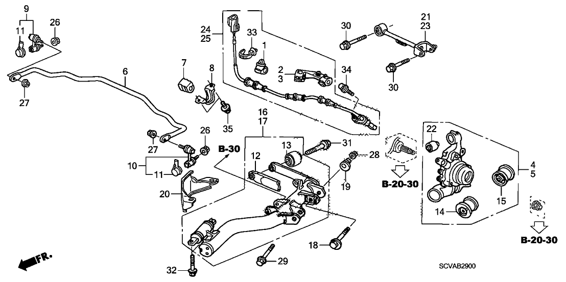
Let's dive deep into the rear suspension system of the 2005 Honda CRV. This article provides a detailed look at the rear suspension diagram, offering insights for repairs, modifications, or simply understanding how this crucial system functions. Having this knowledge empowers you to tackle DIY projects with confidence and diagnose issues more effectively.
Purpose of Understanding the Rear Suspension Diagram
The rear suspension diagram of your 2005 CRV isn't just a pretty picture; it's a vital resource for several reasons:
- Repair and Maintenance: Identifying components quickly when performing repairs, such as replacing worn bushings, struts, or control arms.
- Troubleshooting: Diagnosing suspension problems like excessive bouncing, uneven tire wear, or strange noises.
- Modifications and Upgrades: Planning and executing suspension upgrades, such as installing aftermarket springs, shocks, or sway bars.
- General Knowledge: Understanding the interconnectedness of the system and how each part contributes to ride quality and handling.
Think of the diagram as your roadmap to the rear suspension. Without it, you're navigating blind.
Key Specs and Main Parts
The 2005 Honda CRV utilizes a double wishbone independent rear suspension. This design offers a good balance of ride comfort and handling performance. Key components include:
- Upper Control Arms: These arms connect the wheel hub to the vehicle's frame. They control the upper movement of the wheel and are crucial for maintaining proper wheel alignment.
- Lower Control Arms: Similar to the upper arms, lower control arms manage the lower movement of the wheel hub. They often bear more of the suspension load.
- Shock Absorbers (Struts): These dampen the oscillations of the springs, preventing excessive bouncing and ensuring a smooth ride. A strut typically combines the shock absorber and coil spring into one unit, although on the CRV the spring and shock are separate.
- Coil Springs: These provide the primary suspension support, absorbing bumps and irregularities in the road.
- Trailing Arms: The trailing arms connect the wheel hub carrier to the chassis. They help control wheel movement, especially during acceleration and braking, improving stability.
- Rear Wheel Hub/Bearing Assembly: This unit houses the wheel bearing and allows the wheel to rotate smoothly.
- Stabilizer Bar (Sway Bar): This connects the left and right sides of the suspension. Its purpose is to reduce body roll during cornering, improving handling.
- Bushings: These are rubber or polyurethane components that isolate the suspension components from the chassis, reducing noise and vibration. Bushings are found at the pivot points of control arms and other suspension components.
- Subframe: A structural component that provides mounting points for many of the suspension components. It helps to isolate road noise and vibration from the vehicle's cabin.
Knowing these parts by name and function is the first step in understanding the system. The diagram will visually show how they are arranged.
Diagram Symbols: Deciphering the Language
A suspension diagram is essentially a technical drawing, and it uses specific symbols to represent different components and connections. Understanding these symbols is crucial for accurate interpretation:
- Solid Lines: Typically represent rigid components like control arms, struts, and sway bars. The thickness of the line might indicate the component's relative size or importance.
- Dashed Lines: Often indicate hidden or obscured components, or sometimes represent lines of motion or reference.
- Circles and Dots: Usually represent pivot points or connection points between components, such as where a control arm connects to the frame or hub. These will often indicate the location of bushings.
- Hatching or Cross-hatching: Can indicate the material of a component (e.g., cast iron, aluminum).
- Arrows: Show the direction of movement or force.
- Labels and Abbreviations: Diagrams will have abbreviations like "UCA" (Upper Control Arm), "LCA" (Lower Control Arm), "SB" (Sway Bar), etc. Always refer to a legend if one is provided.
- Color Coding (if applicable): Some diagrams use color to differentiate between different types of components or systems. For example, one color might represent hydraulic lines, while another represents electrical wiring. However, most typical suspension diagrams are black and white.
Take some time to familiarize yourself with the symbols used in your specific 2005 CRV rear suspension diagram. A legend, if present, is your best friend.
How It Works: A Simplified Explanation
The rear suspension of the 2005 CRV is designed to provide a comfortable ride while maintaining stable handling. Here's a simplified explanation of how it works:
- Wheel Movement: When the wheel encounters a bump, it moves vertically.
- Spring Compression: The coil spring compresses, absorbing the energy of the bump. The spring rate dictates how much force is needed to compress the spring a given distance.
- Shock Absorption: The shock absorber (strut) dampens the spring's oscillations, preventing the vehicle from bouncing excessively. It converts the kinetic energy of the suspension movement into heat.
- Control Arm Movement: The upper and lower control arms control the wheel's movement arc, helping to maintain proper wheel alignment throughout the suspension's travel. They allow for independent movement of each wheel, improving ride quality.
- Sway Bar Action: During cornering, the sway bar resists body roll by transferring force from one side of the suspension to the other. This helps to keep the vehicle more level and improves handling.
- Trailing Arm Contribution: The trailing arm helps with stability during braking and acceleration, minimizing unwanted wheel movement.
- Bushing Function: Bushings isolate the frame from the harsh vibrations of the road. They work as dampeners and should be checked periodically for degradation.
The system works in concert to provide a balanced and controlled ride.
Real-World Use: Basic Troubleshooting Tips
Here are a few troubleshooting tips using the rear suspension diagram:
- Clunking Noises: Often caused by worn bushings, loose bolts, or damaged ball joints (though ball joints are less common in the rear). Use the diagram to locate the bushings in the control arms and sway bar links. Inspect them for cracks, tears, or excessive play.
- Excessive Bouncing: Usually indicates worn shock absorbers. Visually inspect the shocks for leaks or damage.
- Uneven Tire Wear: Can be caused by misaligned suspension components (e.g., bent control arm, worn bushings). The diagram helps you visualize the geometry of the suspension and identify potential problem areas. Professional alignment is crucial in these cases.
- Sway Bar Disconnect: Examine the points where the sway bar attaches to the suspension. Check for broken links or damaged bushings.
Always start with a visual inspection, referring to the diagram to pinpoint potential problem areas. Remember that suspension problems can also affect braking and steering, so address them promptly.
Safety Considerations
Working on the rear suspension can be dangerous if proper precautions aren't taken. Here are some key safety points:
- Spring Compression: Never attempt to disassemble a strut without a proper spring compressor. The compressed spring stores a tremendous amount of energy and can cause serious injury if released uncontrollably. Only qualified professionals should disassemble struts.
- Jacking and Supports: Always use a jack rated for the weight of your vehicle and place it on a solid, level surface. Use jack stands to support the vehicle before working underneath it. Never rely solely on a jack.
- Torque Specifications: Always tighten suspension components to the manufacturer's specified torque. Use a torque wrench to ensure accurate tightening. Over-tightening can damage components, while under-tightening can lead to loosening and failure. These specifications can be found in the vehicle’s service manual.
- Brake Lines: Be careful not to damage brake lines when working on the suspension. Damage to a brake line can result in brake failure.
- Wheel Alignment: After making any significant changes to the suspension, it's essential to have the wheel alignment professionally checked and adjusted.
Suspension work requires caution and attention to detail. If you're not comfortable performing a specific task, seek professional assistance.
Understanding the 2005 Honda CRV's rear suspension diagram is a valuable asset for any DIYer or car enthusiast. It provides a clear visual representation of the system's components and how they work together. By familiarizing yourself with the diagram and following safe work practices, you can confidently tackle repairs, upgrades, and maintenance tasks.
We have the full, high-resolution diagram available for download. You can use it as a reference guide during your repairs and modifications. Contact us for access.